Environmental Engineering Reference
In-Depth Information
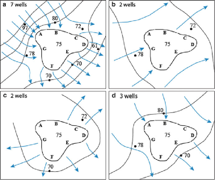
Fig. 3.23 Groundwater equipotential lines and flowlines based on (a) seven wells, (b) two wells,
(c) a different combination of two wells, and (d) three wells
D, and F), inflow would total just over 62,000 m
3
/day and outflow would total just
over
43,000 m
3
/day. Groundwater discharge to the wetland would be more than
double the estimate based on seven monitoring wells and flow of wetland water to
groundwater would be only two-thirds of groundwater discharge. It is clear that the
location and number of monitoring wells are crucial for determining a reasonably
accurate indication of groundwater exchange with a wetland.
The segmented-Darcy approach assumes that groundwater flow vectors are per-
pendicular to the wetland shoreline. This clearly is not the case for some wetland
settings, including the example shown in Fig.
3.22
. Groundwater flow is primarily
tangential to shoreline segments B and G, where hinge lines are located. Those hinge
lines also indicate that, not only is the hydraulic gradient not uniform along the entire
segment reach, the gradient is in opposite directions from one end of the segment
to the other. Contouring the hydraulic-head data and drawing flowlines provides
additional information about groundwater exchange with the wetland. For example,
flowlines can provide a much better indication of the locations of hinge lines.
Knowing that, shoreline segments can be modified to end in the vicinity of hinge
lines and more realistic values of flow can be determined for each shoreline segment.