Biomedical Engineering Reference
In-Depth Information
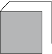
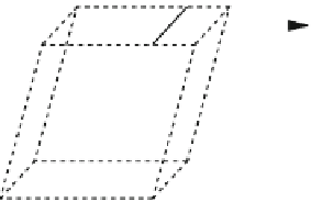
Fig. 7.3
A block subject to
shear stress that distorts the
shape in a way that its
cross-sectional area changes
from a
square
to a
parallelogram
L
A
T
L
i
f
e
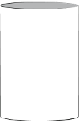
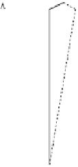
Fig. 7.4
Torque of force
T
applied to a cylinder fixed
on the
bottom
r
T
h
magnitude, i.e.,
T
f
s
, and in the opposite direction, as shown in Fig.
7.3
. The
shear stress is defined as
¼
T
/
A,
where
A
is the area of the surface. The magnitude
of the deformation is given by the shear strain, defined as
ε ¼ Δ
σ ¼
L
is
the horizontal dislocation of the surface that undergoes shear and
L
i
is the initial
height of the block, as can be seen in Fig.
7.3
.
The shear modulus,
S
, is given by:
L
/
L
i
where
Δ
T
A
ΔL
¼
σ
S
ε
¼
L
i
:
(7.5)
(block inclination
measured in radians). Observe that the shear force is always parallel to the area
A
.
The values of the shear modulus of some materials are given in Table
7.1
.
Generally, the value of
S
is between
Y
/2 and
Y
/3, meaning that it is easier to deform
solids with shear stress than with tensile or compressive stress.
Another type of stress is the torsion stress that can cause a deformation similar to
that produced by shear stress. In the case of shear, the force is applied parallel to the
area
A
, while in the case of torsion, the torque is applied in the direction of rotation.
In this case,
the shear strain
ε ¼ Δ
L
/
L
i
¼
tan
ϕ ϕ