Biomedical Engineering Reference
In-Depth Information
corrected
optics. Otherwise, the MTFs of indi-
vidual system components are all cascaded by
multiplication. The concept of aberration tole-
rance should be considered: How much aberration
can be considered acceptable within the system
requirements? Smith
[8]
advises that most imag-
ing systems can withstand aberration resulting in
up to one-quarter wavelength of optical path dif-
ference from a perfect (i.e., ideal) reference wave-
front without a noticeable effect on image quality.
High-quality optics typically achieve this goal
[9]
.
of each photodetector, and the spatial sampling
of the continuous image. For compactness, a one-
dimensional approach is used where appropriate
for the explanation that follows.
Each photodetector of the FPA must have a
large enough photosensitive area to capture a
sufficient number of photons to obtain a useable
signal above the noise floor. This finite area
results in spatial integration that produces a
blurring or smearing effect. In the most common
case, the sensitivity of the photodetector is rela-
tively constant over the entire photosensitive
area, so the effective PSF of the FPA is just a
rectangular (or
top-hat
) function with a width
determined by the size of the photosensitive area
in the given dimension for the individual photo-
detectors. The OTF of the FPA is the Fourier
transform of a rectangular function, which is the
well-known sinc function. Thus, the MTF of the
FPA is the magnitude of the associated sinc:
1.2.2.4 Detector Arrays
With a scene imaged at the focal plane, the next
step is to use some photosensitive devices to con-
vert the light energy to electrical energy. One of
the most common techniques is to use a rectangu-
lar, planar array of photodetectors (typically CCD
or CMOS) at the focal plane; this is often called a
focal plane array
(FPA). Use of the FPA introduces
two more effects on the image: the spatial inte-
gration of light over the finite photosensitive area
sin(π
x
d
u
)
=|sinc(
x
d
u
)|,
MTF
FPA
=
(1.8)
π
x
d
u
1
0.9
1
0.8
0.8
0.7
0.6
0.6
0.5
0.4
0.4
0.2
0.3
0
4
0.2
2
4
2
0.1
0
0
−2
0
−2
0
2
4
−4
−4
Normalized spatial frequency, 1/x
d
units
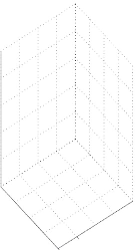
FIGURE 1.10
Normalized MTF of a typical focal plane array with a square photosensitive area, where
x
d
=
y
d
. The spatial
frequency units of the horizontal axes (
u
,
v
directions) are the reciprocal of the spatial dimension of a single photodetector
in that direction, as in
1/
x
d
or
1/
y
d
, respectively.


