Biomedical Engineering Reference
In-Depth Information
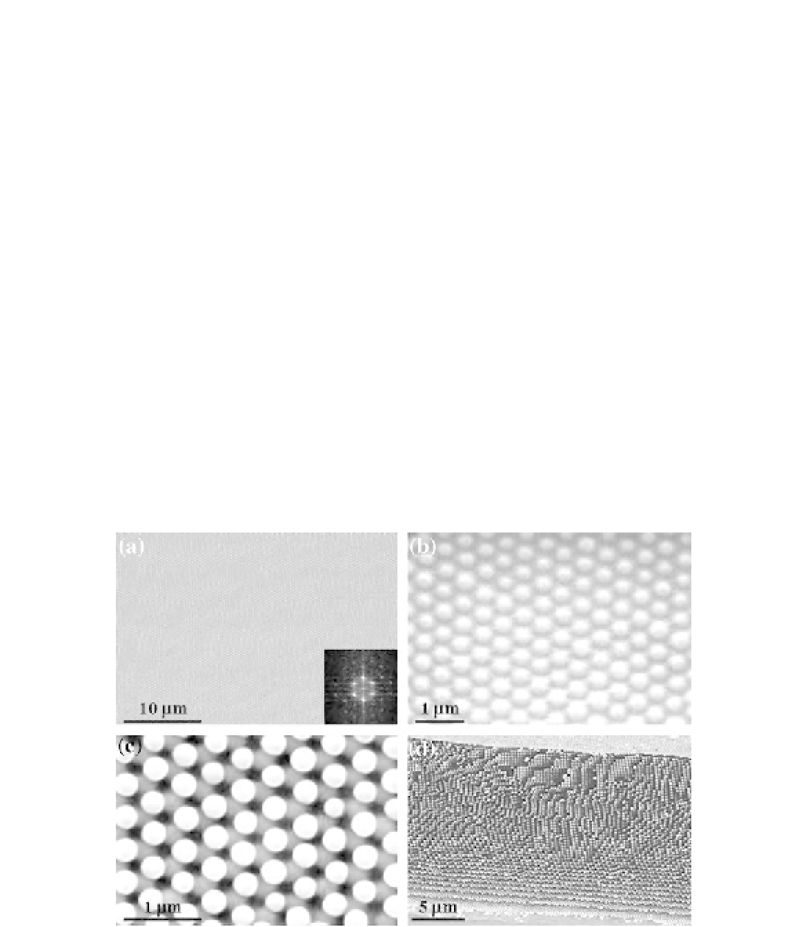
then rapidly polymerized to form 3D ordered
polymer nanocomposites (
Figure 12.2
). A scan-
ning electron microscope (SEM) image (
Figure
12.3
a) and its Fourier transform (inset of
Figure
12.3
a) demonstrate the highly ordered structures
with hexagonal packing on the film surface.
At higher magnification (
Figure 12.3
b),
another interesting feature is evident, i.e., the
spheres of the top layer are not contacting with
each other, but they exhibit center-to-center
distance around 1.41
D
, where
D
is the diameter
of colloids. The non-close-packing of colloids
and the specific spacing between intra-layer
spheres are much more apparent after the
polymer matrix is selectively removed by
conventional oxygen plasma etching. As shown
in
Figure 12.3
c, the top-layer spheres only fill in
the triangularly arranged crevices made by the
non-touching spheres of the underneath layer.
This non-close-packed structure is indeed
exhibited by all layers of the spin-coated
colloidal crystal. The ordering perpendicular to
the substrate surface is apparent in the cross-
sectional SEM image (
Figure 12.3
d).
Besides the unusual non-close-packed crys-
talline structure, the spin-coating technology
enables rapid production of wafer-sized colloi-
dal crystals with highly uniform and tunable
thickness ranging from a single monolayer to
hundreds of monolayers
[98, 99]
. The crystal
thickness can be easily adjusted by tuning the
spin speed and duration. The crystal thickness
is inversely proportional to the spin speed and
the square root of the spin duration. For instance,
colloidal crystals consisting of 325-nm-diameter
silica spheres with 2, 5, and 41 colloidal multi-
layers can be fabricated by spin coating at
6,000 rpm for 900, 170, and 120 s, respectively.
The typical spin-coating condition to assemble
submicrometer-sized particles into monolayer,
non-close-packed colloidal arrays (
Figure 12.4
)
is 8,000 rpm for 5-6 min.
FIGURE 12.3
(a) Typical top-view SEM image of a spin-coated colloidal crystal-polymer nanocomposite film. The inset
shows a Fourier transform of a 40
×
40
μ
m
2
region. (b) Higher-magnification image. (c) Typical top-view SEM image of a
released multilayer colloidal crystal after removing polymer matrix. (d) Cross-sectional SEM image of the released colloidal
crystal. Adapted from Ref.
98
.