Biomedical Engineering Reference
In-Depth Information
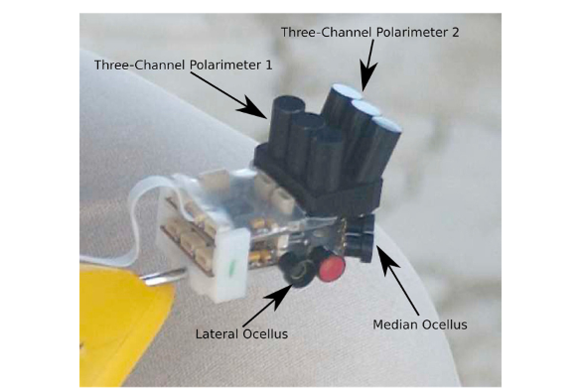
FIGURE 9.5
Integration of the ocelli and polarization sensors is designed to provide improved compass measurements
and precise control of roll angle by stabilizing the sensor in the roll direction.
with individual variations of
bias
above 0 volts
when responding to darkness and individually
varying scale factors or
gains
. Not only do the
light-sensitive elements differ from each other,
but the supporting electronics will have the
same variables. To simplify the discussion, we
consider how direction is computed from three
individual assemblies of a photodiode, a polari-
zation filter, and an electronic amplifier. We
assume for now that the polarization filters on
each assembly are aligned at known angles with
respect to an external reference.
We represent the response of each photode-
tector to incident light in terms of voltage
which includes the scalar response
q
to unpolar-
ized light, which is a result of optical input, and
a scalar bias term
b
that is an electrical signal.
The response of the sensor to the polarized com-
ponent of the light is given by
P
·
F
, where
F
is
a two-dimensional Cartesian vector represent-
ing the orientation of the polarization axis of the
filter (as the direction of the vector given by
∠
F
= TAN
−1
F
x
/
F
y
) and its attenuation as
||
F
||
.
Similarly,
P
is a vector representing the direction
and magnitude of the incident polarized light.
The maximum response occurs when
F
and
P
are parallel and the minimum when the two
vectors are orthogonal.
To eliminate electronic and optical biases,
b
and
q
, the difference between the responses of
the three samples
v
1
to
v
3
is taken; thus,
v
=
b
+
P
·
F
+
q
,
(9.1)