Biomedical Engineering Reference
In-Depth Information
1.2.1 Basic Optics and Sensors
1.2.1.1 Object and Image Distances
the distance to the image plane
s
i
is equal to the
focal length
f
. The term
optical infinity.
is used to
describe an object distance that results in an
image plane distance very close to the focal
length; for example, some designers use
s
o
100
f
as optical infinity, since in this case
s
i
is within
1% of
f
. On the other hand, for visual acuity
exams of the human eye, optometrists generally
use
s
o
≈ 338
f
as optical infinity.
Equation
(1.1)
is also useful for calculating
distances perpendicular to the optical axis (i.e.,
transverse distances). Similar triangles provide
the relationship
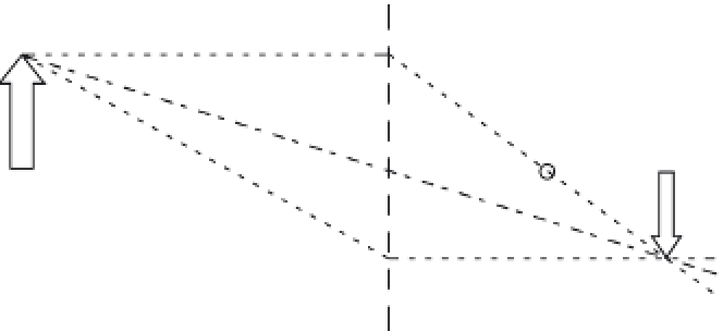
An image can be formed when light, reflected
from an object or scene (at the object plane),
is brought to focus on a surface (at the image
plane). In a camera, the film or sensor array is
located at the image plane to obtain the sharpest
image. One way to create such an image is with
a converging lens or system of lenses. A sim-
plified diagram of this is shown in
Figure 1.1
,
which identifies parameters that are helpful for
making some basic calculations. One such basic
calculation utilizes the Gaussian lens equation
x
o
s
o
=−
x
i
s
i
,
(1.2)
1
s
o
+
1
s
i
=
1
f
,
(1.1)
which allows calculation of
x
o
or
x
i
when the
other three values are known. The minus sign
accounts for the image inversion in
Figure 1.1
.
Modern cameras and vision sensors based on the
mammalian camera eye typically place a focal
plane array (FPA) of photodetectors (e.g., an
array of either charge-coupled devices (CCD) or
CMOS sensors) at the image plane. This array
introduces spatial sampling of the image, where
the center-to-center distance between sensor loca-
tions (i.e., the spatial sampling interval) equals
the reciprocal of the spatial sampling frequency.
Spatial sampling, just like temporal sampling, is
limited by the well-known sampling theorem:
Only spatial frequencies in the image up to
which assumes the object is in focus at the image
plane. Equation
(1.1)
is based on the simple opti-
cal arrangement depicted in
Figure 1.1
contain-
ing a single thin lens of focal length
f
but can be
used within reason for compound lens systems
(set to the same focal length) where the optical
center (i.e., nodal point) of the lens system takes
the place of the center of the single thin lens
[7]
.
Note that focal length and most other optical
parameters are dependent on the wavelength
λ
.
The focal length is usually known, and given
one of the two axial distances (
s
o
or
s
i
) in
Figure 1.1
,
the other axial distance is easily calculated. When
the distance to the object plane
s
o
is at infinity,
S
o
S
i
x
o
Image
Object
x
i
f
f
FIGURE 1.1
Optical distances for object (
s
o
) and image (
s
i
) with a single lens of focal length
f
.