Biomedical Engineering Reference
In-Depth Information
shaft-driven rotors. For the pure rotation and
combined flapping/rotation tests, rigid blades
with a circular arc profile were tested. Com-
pared to the pure rotation cases, an increase in
thrust of up to 20% and a decrease in torque of
up to 30% were measured during combined
flapping/rotation. Several recommendations
were made for future research leading to a
flight-capable prototype.
Although the concept of active blade flapping
has been shown to enhance the performance of
a conventional rotor, the main challenges to this
approach are the mechanical complexity of the
rotor hub, the inertial forces due to active blade-
flapping, and the additional power required by
the blade-flapping mechanism. These challenges
must be addressed appropriately to enable flight
testing of such a configuration.
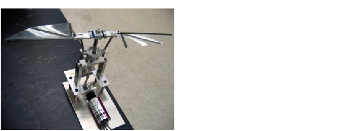
FIGURE 5.17
Bench test prototype of the Flotor, a micro
rotor powered by blade flapping
[65]
.
flapping amplitude at a given collective pitch
setting. Note that rotor thrust was insensitive to
flapping amplitude at a constant collective pitch.
Future work should focus on increasing the
thrust produced by the rotor by operating at
higher rotational speed.
Fitchett and Chopra
[65]
developed a micro-
scale rotor, called the Flotor, that was powered by
blade flapping (
Figure 5.17
). A prototype was
constructed and tested in three modes: pure flap-
ping, pure rotation, and combined flapping/rota-
tion. The geometry of the blades of the Flotor, as
well as the rotational speed, was determined
based on the wings of bats of similar size and
their reduced frequency in cruise flight. The pro-
totype rotor had two blades that were flapped in
phase, a rotor radius of 80 mm, and a blade aspect
ratio of 6.5. To ensure that pure flapping initiated
rotor rotation in the correct direction, the blades
were constructed with a main spar at the leading
edge. This resulted in sufficient elastic twist in
the blades to generate the appropriate propulsive
forces at low rotational speed. The blades were
constructed out of 0.25 mm thick mylar sheet and
a carbon fiber framework.
In the pure flapping mode (passive rotation),
a maximum disk loading of 10 N/m
2
was meas-
ured, which is low compared to conventional
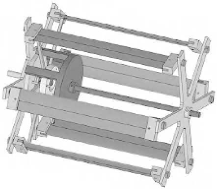
5.5.5 Cycloidal Rotor
The cycloidal rotor is an unconventional lift-
producing mechanism that has the potential to
improve hover efficiency by harnessing unsteady
aerodynamic effects. A cycloidal rotor consists of
several blades that rotate about a horizontal axis
Blades
Direction
of rotation
Direction of flight
FIGURE 5.18
Cycloidal rotor configuration.