Biomedical Engineering Reference
In-Depth Information
(a)
0.3
Mean camber line
Airfoil shape outline
Centroid
0.2
0.1
0
−0.1
−0.2
−0.8
−0.6
−0.4
−0.2
0
0.2
0.4
0.6
0.8
Chordwise location, chord, c=1.6
0.3
(b)
Mean camber line
Airfoil shape outline
Centroid
0.2
0.1
0
−0.1
−0.2
−0.8
−0.6
−0.4
−0.2
0
0.2
0.4
0.6
0.8
Chordwise location, chord, c=1.6
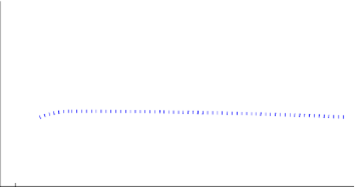
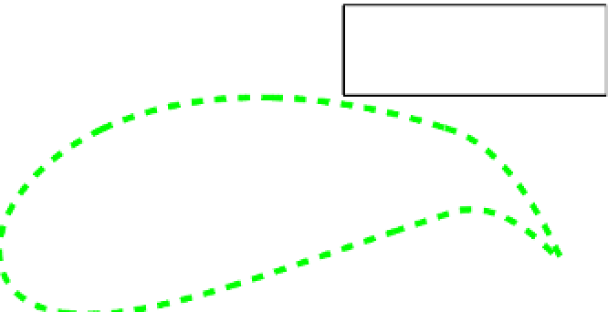
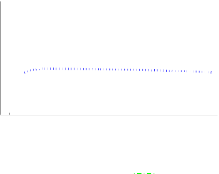
FIGURE 4.4
(a) Thickness control of a morphing airfoil, and (b) camber control of the morphing airfoil.
in generating lift on a wing. There are methods
of affecting and altering shape. Typically, these
involve the use of (1) multiple serial manipulators
with rigid links, (2) multiple serial manipulators
with elastic links, and (3) dynamically controlled
morphing elastic/smart structures.
Figure 4.3
illustrates a typical airfoil actuated by a truss-
like assemblage of rigid-link actuators
[14]
. The
upper and lower surfaces are actuated by inde-
pendent serial manipulators while the thickness
is controlled by a set of extendable actuators.
The morphing schedule is defined by a series
of standard airfoil shapes. For example, a typical
morphing schedule of NACA airfoil shapes is
1112, 1115, 1118, 4418, and 8818. NACA 1112 is a
slightly cambered 12% thick airfoil. The thick-
ness and camber morphing sequences are illus-
trated in
Figure 4.4
. First, as shown in
Figure
4.4
a, the thickness is increased to 15% (NACA
1115) and then to 18% (NACA 1118). Then, as
shown in
Figure 4.4
b, the thickness is held at
18% and the maximum camber is increased from
1 to 4 and then to 8 (the first digit; the second
digit defines the location of maximum camber).
To secure the benefits of morphing, one would
ideally like to morph from a low-speed airfoil
such as NACA 0012 to a supercritical airfoil at
transonic speeds such as NASA SC(2) 0712