Information Technology Reference
In-Depth Information
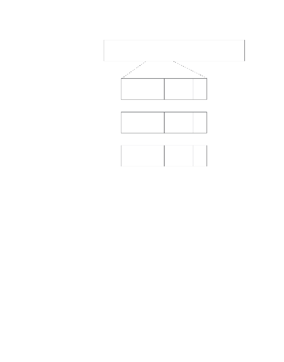
Figure10-1 The SDLC Frame Format
Field length,
in bytes
1
1 or 2
1 or 2
Variable
2
1
Flag
Address
Control
Data
FCS
Flag
Information
frame format
Receive
sequence
number
Send
sequence
number
Poll
final
0
Supervisory frame format
Receive
sequence
number
Poll
final
Function
code
0
1
Unnumbered frame format
Function
code
Poll
final
Function
code
1
1
As Figure 10-1 shows, SDLC frames are bounded by a unique flag pattern. The Address field always
contains the address of the secondary involved in the current communication. Because the primary is
either the communication source or destination, there is no need to include the address of the primary—it
is already known by all secondaries.
The Control field uses three different formats, depending on the type of SDLC frame used. The three
SDLC frames are described as follows:
•
Information (I) frames
—These frames carry upper-layer information and some control
information. Send and receive sequence numbers and the poll final (P/F) bit perform flow and error
control. The send sequence number refers to the number of the frame to be sent next. The receive
sequence number provides the number of the frame to be received next. Both the sender and the
receiver maintain send and receive sequence numbers. The primary uses the P/F bit to tell the
secondary whether it requires an immediate response. The secondary uses this bit to tell the primary
whether the current frame is the last in its current response.
•
Supervisory (S) frames
—These frames provide control information. They request and suspend
transmission, report on status, and acknowledge the receipt of I frames. They do not have an
Information field.
•
Unnumbered (U) frames
—As the name suggests, these frames are not sequenced. They are used
for control purposes. For example, they are used to initialize secondaries. Depending on the function
of the unnumbered frame, its Control field is 1 or 2 bytes. Some unnumbered frames have an
Information field.
The frame check sequence (FCS) precedes the ending flag delimiter. The FCS is usually a cyclic
redundancy check (CRC) calculation remainder. The CRC calculation is redone in the receiver. If the
result differs from the value in the sender's frame, an error is assumed.
A typical SDLC-based network configuration appears in Figure 10-2. As illustrated, an IBM
establishment controller (formerly called a cluster controller) in a remote site connects to dumb
terminals and to a Token Ring network. In a local site, an IBM host connects (via channel-attached