Graphics Programs Reference
In-Depth Information
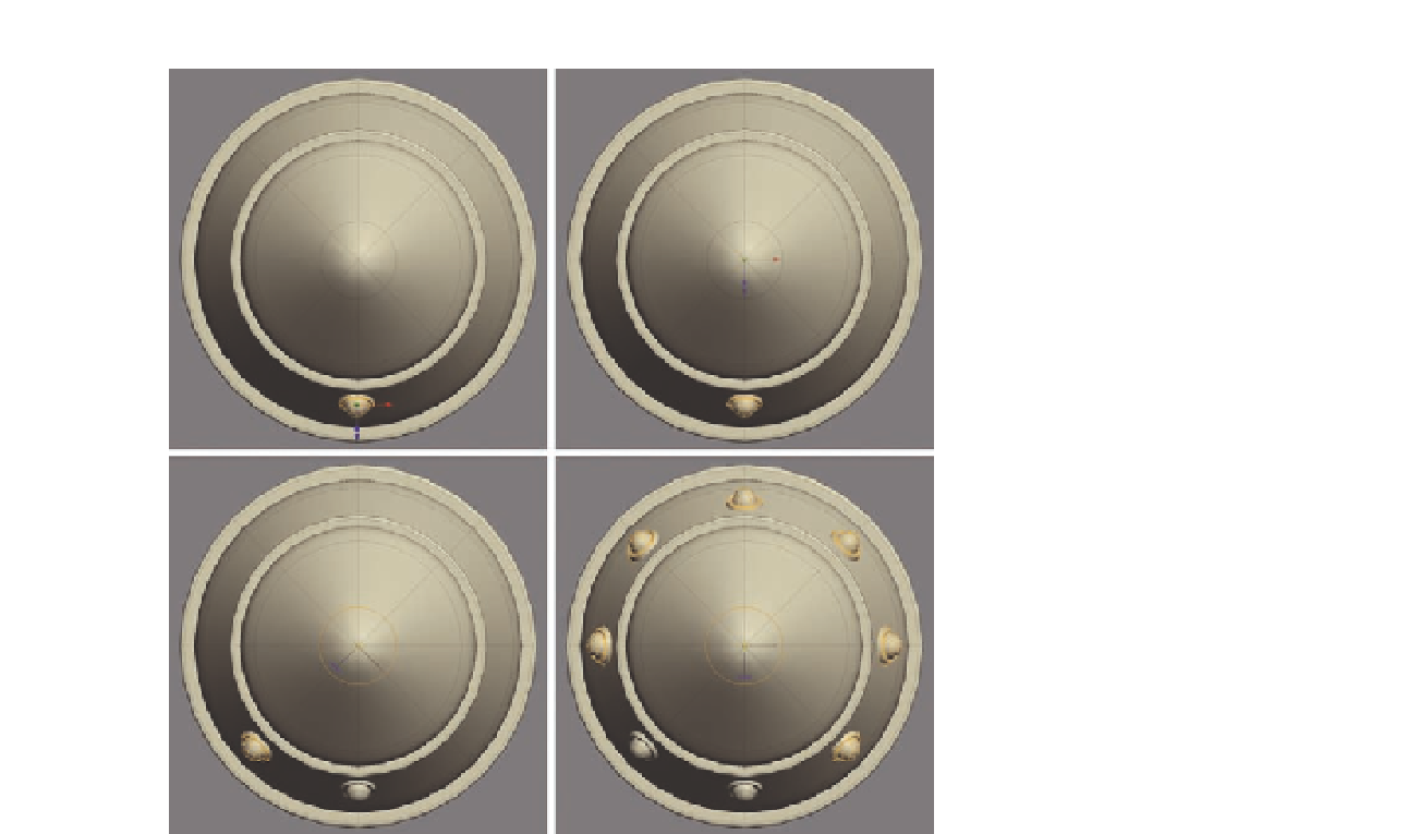
FIG. 10.5
Duplicate this rivet to
create more around the rocket.
●
You can now start to work in more details, like adding the bands around
the rocket that will eventually hold it in place (Figure 10.6). These are
simple cylinders with beveled edges.
Now we will focus on the base of the rocket, where we need to add the
exhausts and a lip around the end to make it feel more solid.
●
To create the lip, i rst
Extrude
the end edges inward, and then again back
up into the model (Figure 10.7).
●
Bevel
the lower edges next to harden the appearance of the surface.
●
To create the exhausts, which are built from three sections, simply modify
a cylinder making it into a tapered tube shape, and duplicate it to create
the lower two (Figure 10 7e).
●
Remember to edit the i nal exhaust, creating internal polygons so you
can't see through the model (Figure 10.7f ).
●
The main rocket is in place, so why not work on it a little more to add in
some more details. As you can see in Figure 10.8, we also added some
pipes and bolts around the rims to make it a little more interesting.
●
When you are satisi ed, use the
Mirror Geometry tool
to generate the
rocket for the opposite side.