Graphics Reference
In-Depth Information
14.
Click
Finish Sketch
.
15.
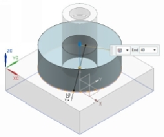
Activate the
Extrude
tool and extrude the sketch up to 40.
16. Click the
Part Navigator
tab on the Resource Bar and notice the
Linked Com-
ponent Curve(1)
.
17. In the
Assembly Navigator
, double-click on
Tutorial 1
to switch to the assembly
mode.
Creating the third Component of the Assembly
1.
On the ribbon, click
Assemblies > Component > Create New
.
2.
Select the
Model
template, type
Head Screw
in the
Name
box, and click
OK
twice.
3.
In the
Assembly Navigator
, right click on
Head Screw
and select
Make Work
Part
.
4.
Start a sketch on the XZ Plane.