Biomedical Engineering Reference
In-Depth Information
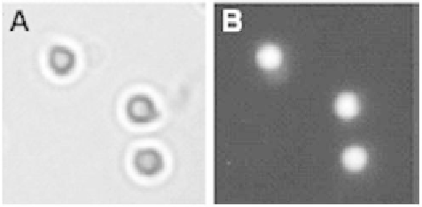
Figure 9.2
Microscope view of fluorescent magnetic beads of 200 nm (a) white light, and (b)
fluorescent image.
fluorescence. Two different approaches to obtain combined magnetic/fluorescent
effect have been followed. The first approach consists of incorporating fluorescent
markers inside the beads during their fabrication (Figure 9.2), but it was found
rather difficult to obtain all the convenient properties of magnetic beads (sphericity,
biocompatiblility, monodispersion, compactness). The second approach consists
of assembling a complex magnetic bead-target-fluorescent bead (Figure 9.3) or in
binding the fluorescent particle directly to the magnetic bead.
The scheme of Figure 9.3 is widely used because it has the advantage of mark-
ing the target directly. Magnetic beads are used to bring the targets into a detection
chamber, and they are usually removed after they have completed their task, so it
is thus advantageous to have the targets linked to a fluorophore for the following
processes, such as detection.
Recently, the principle of a compound particle at the same time magnetic
and fluorescent has been established by [2]. A spherical magnetic nanoparti-
cle built around an iron-platinium core (FePt) is coated by a layer of cadmium
and sulfur (CdS). This bead is heated so it can melt the outer layer of CdS. This
Figure 9.3
Schematic view of the association of magnetic bead carrying 72-bp.DNA and marked
by a fluorescent quantum dot.