Biomedical Engineering Reference
In-Depth Information
However there have been some flow models in special cases that we will present
later in this section. When facing considerable theoretical difficulties, an approach
based on nondimensional scaling numbers helps reveal the physical behavior.
Throughout this section we will use the scaling numbers characteristic of FFDs
already presented in Chapter 1.
Actuation of MFFDs
There are two ways of making the fluids circulate in a MFFD. The flows are either
driven by syringe pumps or by micropumps. In the first case, it is referred as flow
rate actuation; in the second case, it is referred as driving pressure actuation. In the
literature flow rate, actuation is more common because syringe pumps are largely
used in the laboratories. However, recently [71, 72] with the development of reli-
able pressure pumps, pressure actuation has started to be used, with the advantage
of very constant flow rates. It is common to make experiments keeping the ratios
q
*
=
Q
i
/
Q
e
or
p
*
=
P
i
/
P
e
constant. It is emphasized here that there is no equivalence
between theses two types of actuation: we shall see that, in the first case, the capil-
lary numbers ratio
Ca
i
/
Ca
e
=
h
i
Q
i
/
h
e
Q
e
—characterizing the flow behavior—depends on the
viscosity ratio
Ca
i
/
Ca
e
=
h
i
/
h
e
, while in the second case, the ratio
Ca
i
/
Ca
e
is
constant.
The Different Flow Regimes
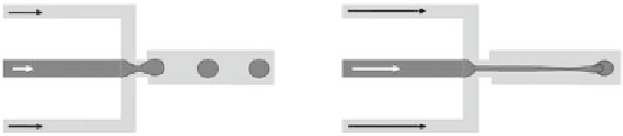
Two different categories of flow regimes exist in a FFD: dripping and jetting. Some
authors, according to their particular geometry of FFD, subdivide these two cat-
egories. In the dripping regime, the flow rates are small enough so that the drop-
let forms immediately after the nozzle. In the jetting regime, a thread or filament
stretches far into the outlet channel (Figure 4.68). In the first case, drops are larger,
with a small coefficient of variation (CV) of the order of a few percents. This is why
the dripping regime is preferred in biotechnology.
The dripping regime occurs at low values of the low rates. Upper limits of
this regime have been investigated in [73, 74]. It appears that two nondimensional
numbers pinpoint the transition to jetting regime: the critical Weber number
We
c
of
the dispersed phase, and the critical capillary number
Ca
c
of the continuous phase.
The first condition for a dripping regime is
2
ρ
U R
i
i
thread
(4.97)
We
=
<
We
c
γ
Figure 4.68
Dripping and jetting regimes. (a) Dripping regime: drops form at the nozzle; (b) jet-
ting regime: drops form at the tip of a long thread.