Biomedical Engineering Reference
In-Depth Information
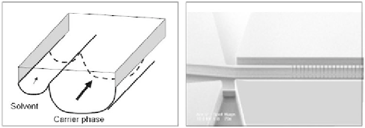
disrupt the interface. Different systems have been imagined to maintain the integrity
of the interface, at least unto a certain level of velocities: the two main categories are
the grooved-channel design [44, 45] and the micropillar-row design [46, 47]. They
are shown in Figure 4.49.
On a general basis, stability depends on the ratio of the capillary numbers of
the two phases
Ca
η
U
γ η
U
η
Q w
1
1
1
1
1
1
1
2
=
=
=
(4.72)
Ca
γ η
U
η
U
η
Q w
2
2
2
2
2
2
2
1
Thus stability requires adapted ratios of the capillary numbers; but because the
secondary phase is flowing at a very low velocity, it is not possible to have a ratio
between the two capillary numbers close to 1 unless the dominant velocity of the
carrier phase is limited and the length of the device not too long. This leads to a
second difficulty, which is the efficiency of the system. A limited length of channel
means a limited interfacial area and a limited transfer to the secondary phase. An
analysis of this trade-off is in [49]. In general, the efficiency of the system is related
to the length of the channels by an exponential relation of the type
æ
ö
D L
eff
= -
1 exp
-
K
w U
(4.73)
ç
÷
2
è
ø
1
1
where
D
is the diffusion coefficient of the targets in the carrier phase,
L
the length of
the system,
w
1
the width of the carrier channel,
U
1
the velocity of the carrier fluid,
and
K
a nondimensional coefficient related to the geometry of the system.
4.3.10 Example of Three-Phase Flow in a Microchannel: Droplet Engulfment
Plugs transported by an immiscible carrier fluid have been used to perform biologi-
cal and chemical reactions in microvolumes [50]. Figure 4.50 shows the principle of
such reactions. Different reagents transported by independent plugs are successively
mixed with a solution containing a chemical or biochemical species. A condition for
a proper functioning of such plug flow reactions is that the plugs do not coalesce.
Coalescence would bring contamination between the liquids. In order to keep the
Figure 4.49
(a) Microgutters for LLE [45]; (b) immiscible microflows separated by a row of pillars
[46] (photo by N. Sarrut, CEA-LETI).