Global Positioning System Reference
In-Depth Information
otherwise absent. Note that the performance of real acquisition algorithms are evaluated in
terms of
Probability of Detection
and
Probability of False Alarm
.
It is important to highlight that for civilian GNSS signals (i.e. GPS L1 C/A, Galileo E1-B), the
spreading code contained in
[ ]
I
y n
is a periodic sequence with period equal to the code
period
T
(i.e. 1 ms for the GPS L1 C/A code, 4 ms for the Galileo E1-B): therefore the delay
τ can be estimated only in the range (0,
T
. In practice only a portion of this infinite
sequence enters into the summation in equation (7) (i.e. the samples of t
he
portion of signal
under test for
n = 0,…,L - 1
). This means that for a given value of
f
, the correlation
assumes the form of a circular correlation when the interval
(0,L
−
1)
contains an integer
number of code periods. This remark is quite important and helps to understand why real
acquisition systems are based on Fast Fourier Transforms (FFTs). In fact, FFTs are used to
implement fast circular correlations and scan the search space efficiently. Insights on the
design of FFT-based signal acquisition system is out of scope for this chapter. However, one
can find many algorithms proposed in recent literature and can refer to (Borre et al., 2006)
for didactical examples.
)
3.2 Code and carrier tracking
Digital receivers sample the analog signal and split the stream of samples over different
digital channels. As seen above, the first step in GNSS processing is the signal acquisition:
the satellites in view are detected and a first rough estimation of the Doppler shift and code
delay is performed. The signal tracking follows the signal acquisition. Most of the receivers
use a Delay Lock Loop (DLL) to synchronize the spreading code from each satellite
(Parkinson & Spilker, 1996), while a Phase Lock Loop (PLL) is generally employed to track
the phase of the incoming carrier. The theory behind digital tracking loops is reported in
many topics (Kaplan & Hegarty, 2006; Parkinson & Spilker, 1996). Here the signal tracking is
only introduced to give fundamentals for the following sections.
Roughly speaking, the signal tracking relies on the properties of the signal correlation and is
fundamental to demodulate the navigation message and estimate the range between the
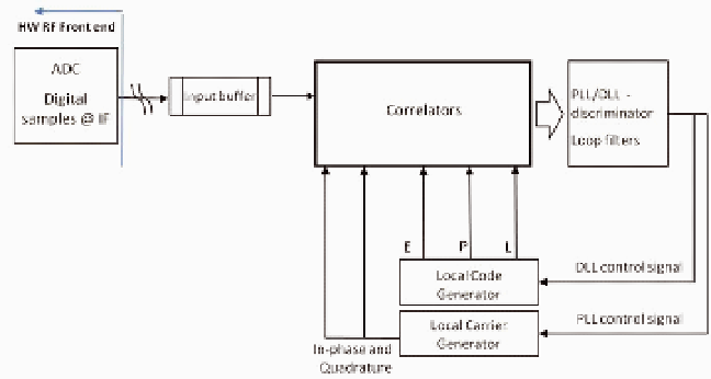
user and the satellites. A generic block diagram of the code and carrier tracking system for
GNSS receivers is shown in Fig. 3.
HW RF Front end
ADC
Digital
samples @ IF
PLL/DLL -
discriminator
Loop filters
Input buffer
Correlators
E P L
Local Code
Generator
DLL control signal
PLL control signal
Local Carrier
Generator
In-phase and
Quadrature
Fig. 3. Block diagram of a generic code and carrier tracking system for GNSS receivers


Search WWH ::

Custom Search