Information Technology Reference
In-Depth Information
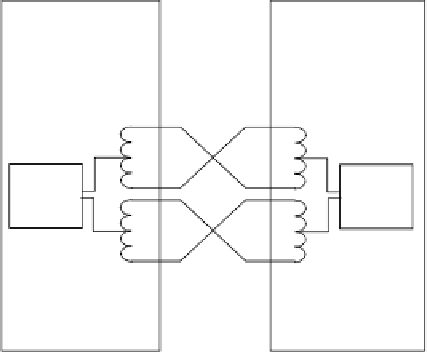
Termination
equipment
Network
termination
NT
1
1
Power
source
3
2
2
3
6
+
R
X
T
X
Power
sink
1
6
3
Power
source
1
5
4
T
X
R
X
-
4
7
5
7
Power
sink
2
Power
source
2
8
8
Figure G.4
Power supplies between NT and TE
48 bits in 250
s
µ
EDAF
A
N
FL
EDS
EDS
ED
L
0
1
0
B1 channel
B2 channel
B1 channel
B2 channel
Figure G.5
ISDN frame format for NT to TE
48 bits in 250
µ
s
LDLF
A
L
FL
LDL
LDL
LD
L
0
1
0
B1 channel
B2 channel
B1 channel
B2 channel
Figure G.6
ISDN frame format for TE to NT
where
F
- framing bit
N
- set to a 1
L -
DC balancing bit
D
- D-channel bit
E -
D-echo channel bit
F
A
- auxiliary framing bit (= 0)
S -
reserved for future use
A
-
activation bit
M -
multiframing bit
B1
-
bits for channel 1
B2
-
bits for channel 2
When transmitting from the NT to the TE, the bits after the
F
/
L
bits, in the B-channel, have a
volition in the first 0. If any of these bits is a 0 then a volition will occur, but if they are 1s
then no volition can occur. To overcome this the
F
A
bit forces a volition. As it is followed by