Information Technology Reference
In-Depth Information
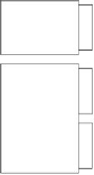
The VXI bus is intended for rack-mounted devices; each slot can take a module that is 30
mm (larger modules can take up more than one slot). Figure 22.4 shows the different sizes of
modules that can be used with the VXI bus. Modules stand on edge, with cooling holes at the
top and bottom edge of each module.
VME (A size)
100x160mm
VXI (D size)
366x340mm
VXI (C size)
233x340mm
VME (B size)
233x160mm
Figure 22.4
VMI module sizes
22.4 VXI bus
The VXI has several buses. These buses are global, unique or private. A global bus is a com-
mon bus that connects to all of the cards. A private bus is used for local communications
between a set of cards, and a unique bus provides additional, named signal lines. The buses
can be grouped as follows:
•
Global - VME computer bus, trigger bus, analogue sum bus and power distribution bus.
•
Private - local bus.
•
Unique - star bus.
22.4.1 Clock and synchronisation bus
This bus contains two clocks and a clock synchronisation signal. One clock operates at
10 MHz, and the other is at 100 MHz, and these are accompanied by a sync signal. Each of
the clocks uses ECL (emitter-coupled logic) and are buffered on the backplane, as illustrated
in Figure 22.5.
22.4.2 Star bus
The star bus allows high-serial communications between each of the modules. It uses two
high-performance ECL lines, named STARX and STARY. The bus is designed so that the
path length between slot 0 and the other 12 slots is the same, and gives a maximum delay of
5 ns between slot 0 and any other module, as illustrated in Figure 22.6.