Information Technology Reference
In-Depth Information
the divisor MSB register. Finally, bit 7 is set back to a '0'. For example, for 9600 baud,
COM1
and 1.8432 MHz clock then
0Ch
is loaded in
3F8h
and
00h
into
3F9h
.
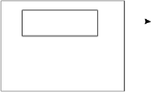
When bit 7 is set at a '0' then a read from the base address reads from the RD buffer and
a write operation writes to the TD buffer. An example of this is shown in Figure 13.9.
Write to TD/RD
buffer
TD
3F8h
TD buffer
RD
3F8h
Read from TD/RD
buffer
RD buffer
Figure 13.18
Read and write from TD/RD buffer
Table 13.5
Serial communications addresses
Primary
Secondary
Register
Bit 7 of LCR
3F8h 2F8h
TD buffer
'0'
3F8h 2F8h
RD buffer
'0'
Divisor LSB
'1'
3F8h 2F8h
3F9h 2F9h
Divisor MSB
'1'
3FBh 2FBh
Line Control Register
Line Status Register
3FDh 2FDh
13.5 RS-232 programs
Figure 13.19 shows the main RS-232 connections for 9 and 25-pin connections without
hardware handshaking. The loopback connections are used to test the RS-232 hardware and
the software, while the null modem connections are used to transmit characters between two
computers. Program 13.2 uses a loop back on the TD/RD lines so that a character sent by the
computer will automatically be received into the receiver buffer. This set-up is useful in test-
ing the transmit and receive routines. The character to be sent is entered via the keyboard. A
CNTRL-D (^D) keystroke exits the program.
Program 13.3 can be used as a sender program (send.c) and Program 13.4 can be used as
a receiver program (receive.c). With these programs, the null modem connections shown in
Figure 13.19 are used.
Note that programs 13.2 to 13.4 are written for Microsoft Visual C++. For early versions
of Borland C/C++ program change
_inp
for
inportb
and
_outp
for
outportb
.