Information Technology Reference
In-Depth Information
Receiving data is similar to the transmission of data, but the lines
DSR
and
DTR
are used
instead of
RTS
and
CTS
. When the DCE wishes to transmit to the DTE the
DSR
input to the
receiver will become active. If the receiver cannot receive the character, it will set the
DTR
line inactive. When it is clear to receive it sets the
DTR
line active and the remote node then
transmits the character. The
DTR
line will be set inactive until the character has been proc-
essed.
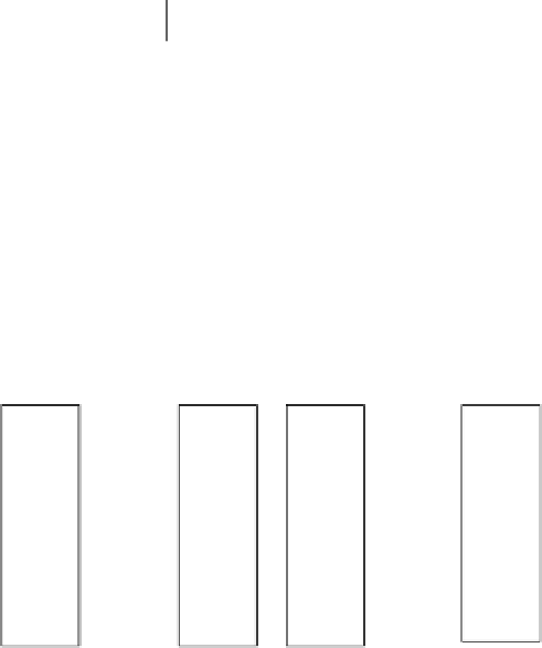
13.3.6 Two-way communications with handshaking
For full handshaking of the data between two nodes the
RTS
and
CTS
lines are crossed over
(as are the
DTR
and
DSR
lines). This allows for full remote node feedback (see Figure
13.12).
9-pin
9-pin
9-pin
25-pin
3
3
3
2
7
8
4
6
5
2
3
4
5
20
6
7
TD
RD
TD
RD
RTS
CTS
DTR
DSR
GND
TD
RD
RTS
CTS
DTR
DSR
GND
TD
RD
RTS
CTS
DTR
DSR
GND
2
2
7
8
4
6
5
7
8
4
6
5
RTS
CTS
DTR
DSR
GND
DTE
DTE
DTE
DTE
Figure 13.12
RS-232 communications with handshaking
13.3.7 DTE-DCE connections (PC to modem)
A further problem occurs in connecting two nodes. A DTE/DTE connection requires cross-
overs on their signal lines, whereas DTE/DCE connections require straight-through lines. An
example computer to modem connection is shown in Figure 13.13.
9-pin
9-pin
9-pin
25-pin
3
3
3
2
TD
RD
TD
RD
TD
RD
TD
RD
2
2
2
3
7
8
4
6
5
7
8
4
6
5
7
8
4
6
5
4
5
20
6
7
RTS
CTS
DTR
DSR
GND
RTS
CTS
DTR
DSR
GND
RTS
CTS
DTR
DSR
GND
RTS
CTS
DTR
DSR
GND
DTE
DCE
DTE
DCE
Figure 13.13
DTE to DCE connections