Information Technology Reference
In-Depth Information
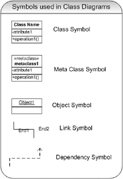
Fig. 13.8 Symbols used in
class diagrams
13.5.2 Use Cases
A use case (a case in the use of the system) depicts pictorially a ''unit of func-
tionality'' of the proposed system. Usually, a use case has two elements, namely,
the use case diagram and a use case description.
Use case diagrams use the symbols depicted in Fig.
13.10
. In use case dia-
grams, an ellipse represents the use case. It is usually accompanied by the name of
the use case and optionally a use case ID. The actor is depicted by the symbol of a
stickman. The stickman is usually identified by a name. The actor could be a
human being interacting with the system using a GUI (Graphical User Interface) or
another system interacting with the system using a machine interface or a protocol.
The interaction between the actors and the use case is represented by lines. The
system boundary is represented by a rectangle. The actor is usually outside the
system.
Figure
13.11
depicts
the
procurements
system
using
use
case
methodology.
The description that accompanies a use case diagram can be a free flowing
scenario description but a structured description is preferable. In whatever form
the organization desires to document the description, it is better to include the
following options in the use case description:
Search WWH ::

Custom Search