Geoscience Reference
In-Depth Information
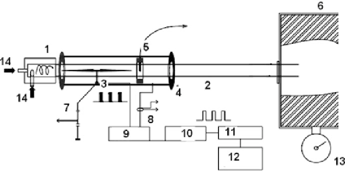
Fig. 6.1
Experimental setup SWT-1.
1
vortex generator,
2
quartz tube,
3
high-frequency electrode,
5
port with pressure sensor,
4
external grounded electrode,
6
vacuum chamber,
7
to high HF power
supply,
8
current probe,
9
HF modulator,
10
-
12
command generator,
13
pressure manometer,
14
gas injector pressure manometer
The modified setup SWT-1F was used to study free longitudinal vortex plasmoids
in the open atmosphere. The high-frequency plasma generator used in this work has
the following parameters: high frequency,
F
HF
,
D
13.6 MHz, high-frequency power,
P
HF
, <2 kW, and two operation modes, a continuous mode and the pulse repetitive
one. DC discharge was also used in some experiments (
U
DC
< 8kV,
I
DC
< 2A).
The typical parameters of the pulsed repetitive high-frequency generator used in
this work are the following: a maximal output pulsed voltage is
60 kV, pulsed HF
power was
1-10 kW, high frequencies are
F
HF1
D
13.6 MHz,
F
HF2
D
0.45 MHz,
pulse repetitive frequency was
F
M
D
10-10
4
Hz, and pulse duration is
T
i
D
10 sto
100 ms.
Plasma and airflow parameters were measured by different diagnostic instru-
ments including a shadow optical device with the excimer KrF laser (œ
D
248 nm),
an optical interferometer with a high-speed camera, Citius (œ
D
638 nm), a voltage
probe and current probe, an optical spectrometer (œ
D
200-800 nm), an MW
interferometer G4-108 (œ
D
1cm),etc.
6.4
Vortex Longitudinal Plasmoid Created
by the Capacity-Coupled High-Frequency Discharge
A homogeneous longitudinal subcritical vortex plasmoid, created by a capacity-
coupled high-frequency discharge in swirl airflow at continuous high-frequency
discharge power pumping, is shown in Fig.
6.2
. The typical length of this plasmoid
varies from 30 to 150 cm at different high-frequency power values. Its diameter is
about 10-15 mm.