Civil Engineering Reference
In-Depth Information
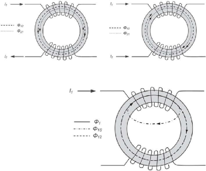
Fig. 2.20
Description of magnetic flows inside a common-mode choke
Fig. 2.21
Stray flows inside
a common-mode choke
result of this, the magnetic flows induced by the chokes and coupled by the core are
in opposite directions as well and cancel each other out. Without a magnetic flow,
no magnetic field can be induced which would lead to an attenuation of the signal.
In case of the common mode, the current directions in the CAN_H and CAN_L
signals have the same directions. This results in an addition of the magnetic flows
which induces a magnetic field which attenuates the common-mode signal parts.
Figure
2.20
depicts the magnetic flows which are proportional to the signal cur-
rents. The magnetic flow Φ
12
depicts the flow induced by the current I1 in choke 1
which influences choke 2. The magnetic flow Φ
21
depicts the flow induced by the
current I2 in choke 2 which influences choke 1.
The above shown function of the CMC does not contain the fact that, due to
straying, the complete magnetic flow will not be transported through the core. The
so-called stray flows are the parts of the complete magnetic flow which do not
influence the magnetic flows induced by the other coil. Figure
2.21
explains the
formation of stray flows. The magnetic flow Φ1 depicts the flow induced by the
current I1. The magnetic flow Φ12 depicts the part of the flow Φ1 which acts in the
other coil, where the magnetic flow Φ1S depicts the flow which does not influence
the other coil.
The strength of the straying is depicted by the stray factor which is standardized
on the rated inductance. The complementary of the stray factor is the coupling factor