Biomedical Engineering Reference
In-Depth Information
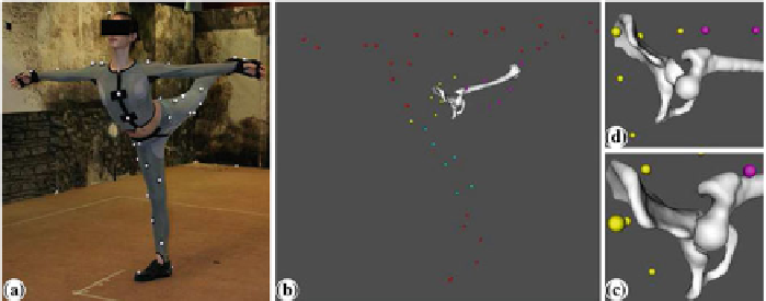
Fig. 10.4 a
Movement recording with the Mocap system and
b
Computed subject posture.
c
A
corrected position by applying the optimization and constraint approach and
d
An error position
(dislocation) due to the STA
×
×
Hz and tracking markers in a 45.3 m3 measurement volume (3.6
3m)(see
Fig.
10.4
). The set of spherical markers (7mm) are placed according to an appropriate
protocol to ensure their visibility to the cameras [
18
]. Unlike other motion acquisition
devices (e.g., intra-cortical pins [
43
], external fixators [
44
], fluoroscopy [
45
]), the
optical system is not invasive and allows the recording of larger ranges of motion.
However, due tomuscle activities and inertial movements, the skinmarkersmove over
the underlying structures. This relative movement represents an artifact, typically
referred to as soft tissue artifact (STA) [
46
]. Consequently, rigid motion of the bone
segment cannot be robustly estimated from the markers trajectories. Correcting these
errors is thus necessary for clinical relevance.
To minimize STA, a nonlinear optimization algorithm [
47
] is used to find, for
each segment and for each frame of movement, the best rigid transformation that
minimizes the error made globally on all the markers. Since it was observed that
joint dislocation may occur due to STA, kinematic constraints allowing some shifts
at the joint are also applied (see Fig.
10.4
c and d). The proposed approach [
48
,
49
]
ensures an accurate kinematical modeling for the hip joint [
28
].
4.2
10.2.3 Physical Modeling
In addition to anatomical and kinematical models, the forces acting on the hip joint
as well as a simulation model are needed to achieve physically-based simulation of
the hip joint.