Biomedical Engineering Reference
In-Depth Information
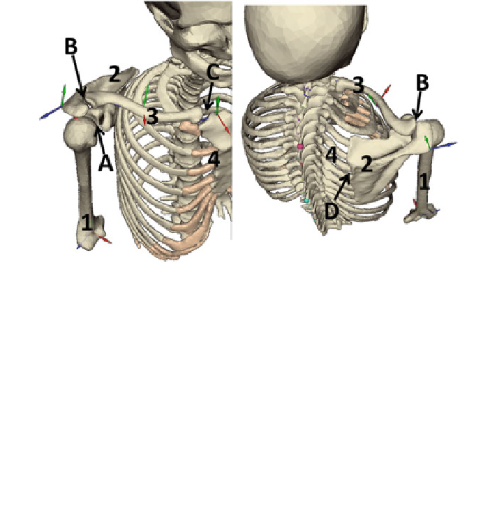
Fig. 9.1
Anatomy of the shoulder joint complex.
Left
: antero-superior view.
Right
: postero-superior
view. See text for explanations.
1
: humerus (Hum);
2
: scapula (Scap);
3
:clavicle(Clav);
4
: thorax
(Thor)
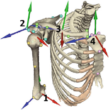
Fig. 9.2
Shoulder bony segments and related anatomical frames (right shoulder, anterosuperior
view).
1
: humerus.
2
: scapula.
3
: clavicle.
4
: sternum/thorax. Conventionally,
Red
/
Green
/
Blue
(RGB) color-coding has been adopted to label the frame axes:
red
=
X-axis,
green
=
Y- a x i s ;
blue
Z-axis. See text for more explanations. Spheres attached to the bones indicate the locations
of key ALs that are used for modeling purposes (see later sections). These ALs are located using
so-called “virtual palpation”. Note that the displayed local frames are according the recommen-
dations of the International Society of Biomechanics [
1
]. The local frames used in this study to
represent motions were slightly different (see section “Construction of anatomical frames”, later in
this chapter)
=