Biomedical Engineering Reference
In-Depth Information
(a)
(b)
(d)
(c)
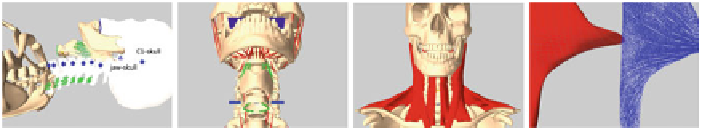
Fig. 6.6 a
Skeleton (
green lines
represent damped springs),
b
Deepmuscles (
red lines
),
c
Superficial
muscles and
d
Muscle fibers
set (see Fig.
6.6
). Our skeletal structure contains the skull, jaw, C1-C7 cervical bones.
First, one to three DOF rotational joints are inserted between adjacent vertebrae, and
the jaw-skull system by carefully locating the pivot points (blue dots in Fig.
6.6
a).
Joints are also limited to a certain range from a study on the human neck [
50
].
Bones that are involved in the neck mechanics are modeled as fixed rigid bodies.
Notice that two extra unilateral planar constraints can be added between the upper
and lower teeth (blue planes in Fig.
6.6
b), hence to resist penetration between jaw
and skull. For stabilization, damped springs can be attached between certain adjacent
vertebrae (green lines in Fig.
6.6
a). At that point, the stiffness of the ligaments can
be included [
51
]. In order to simulate the aspects of the throat, the hyoid, thyroid,
and cricoid bones can be incorporated. A revolute joint (blue cylinder in Fig.
6.6
b) is
created between thyroid and cricoid, and damped springs (green lines in Fig.
6.6
b) are
attached between hyoid-sternum, thyroid-cricoid and cricoid-sternum. The skeleton
structure is then simulated using a multi-body approach.
Then we have to generate the volumetric (e.g. tetrahedral) meshes of our
deformable bodies using a mesher such as TETGEN [
52
]orCGAL[
53
]. Apply-
ing some standard geometrical operations beforehand may be useful, such as
edge
bridge
followed by
fill hole
to fill the holes, and/or employ self-intersection removal
algorithms [
48
,
54
]. In order to obtain more accurate simulations, a maximum tetra-
hedron volume constraint may be needed to ensure that the size of the finite elements
is reasonably small.
Next, muscle fibers can be modeled as polygon curves with a small number of
segments along the direction of muscle contraction. To achieve it, we can select
points at each attachment area to the bone and additional points on the surface of
the polygon mesh. According to the principle that each pair of points should lie
on a line in the direction of muscle contraction, we can pair the points up. Linear
interpolation between two points can then be performed to generate the segments.
Next, Hill's type muscle models (see Sect.
6.2.2.2
) are defined at the segmental scale.
The method proposed by Tan et al. [
55
] can be used to calculate the force on nearby
elements induced by muscle contraction. Figure
6.6
c-d shows an example of muscles
and muscle fibers generated for the trapezius. Finally, the FE models are coupled to
the skeletal system by attaching nodes to the bones.