Graphics Programs Reference
In-Depth Information
y
w
70
0
h
x
20
0
42
0
7
0
α
β
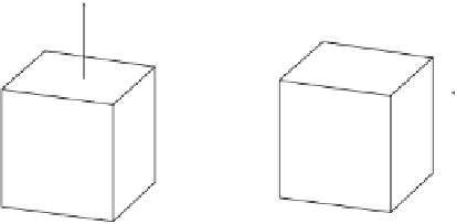
Figure 2.12: The
42
◦
/
7
◦
Dimetric Projection.
What recurrent impressions of the same were possible by hypothesis?
Retreating, at the terminus of the Great Northern Railway, Amiens Street, with con-
stant uniform acceleration, along parallel lines meeting at infinity, if produced: along
parallel lines, reproduced from infinity, with constant uniform retardation, at the
terminus of the Great Northern Railway, Amiens Street, returning.
—James Joyce,
Ulysses
2.3 Oblique Projections
An oblique projection is a special case of a parallel projection (i.e., with a center of
projection at infinity) where the projecting rays are not perpendicular to the projection
plane. We have already seen that axonometric projections show more object details than
orthographic projections but make it more cumbersome to compute object dimensions
from the flat projection. Similarly, oblique projections generally show more object
details than axonometric projections but distort angles and dimensions even more. In
an oblique projection, only those faces of the object that are parallel to the projection
plane are projected with their true dimensions. Other faces are distorted such that
measuring dimensions on them requires calculations.
Figure 2.13 illustrates the principle of oblique projections. A three-dimensional
point
P
=(
x, y, z
) is projected obliquely onto a point
P
∗
on the
xy
plane. We denote
the point (
x, y,
0) by
Q
and examine the angle
θ
between the two segments
PP
∗
and
P
∗
Q
. A cavalier projection is obtained when
θ
=45
◦
and a cabinet projection is the
result of
θ
=63
.
43
◦
.
Because of the special 45
◦
angle, the three shrink factors of a cavalier projection
are equal, as will be shown later. In a cabinet projection, the shrink factors in the
x
and
y
directions (assuming that the object is projected on the
xy
plane) equal 1
/
2.
Figure 2.14a illustrates the geometry of oblique projections and can be used to
derive their transformation matrix. We assume that the projection plane is
z
= 0 (the
xy
plane) and that all the projecting rays hit this plane at an angle
θ
. Two projecting
rays are shown, one projecting the special point
P
=(0
,
0
,
1) to a point (
a, b,
0) and the
other projecting
Q
=(0
,
0
,z
), a general point on the
z
axis, to a point (
A, B,
0). The
origin (0
,
0
,
0) is projected onto itself, so the projection of the unit segment from the


Search WWH ::

Custom Search