Graphics Programs Reference
In-Depth Information
0
.
8165 to obtain actual dimensions on the object. However, the diagram must show the
object (whose main edges are assumed to be originally aligned with the coordinate axes)
after being rotated by
35
.
26
◦
about the
x
axis. If these
rotations result in obscuring important object features, a less restrictive projection, such
as dimetric or trimetric, must be used.
Standards for Axonometric Projections
Several common standards for axonometric projections exist and are described here. We
start with a simple 30
◦
standard for isometric projections whose principle is illustrated in
Figure 2.8. Part (a) of the figure shows a cube projected in this standard after it has been
rotated
φ
=45
◦
about the
y
axis and
θ
=35
◦
about the
x
axis. Part (b) shows the same
cube with dimensions and angles. It is not di
cult to see that
α
satisfies tan
α
=
h/w
,
45
◦
about the
y
axis and by
±
±
which is why
α
=arctan(
h/w
). The standard specifies the ratio
h/w
=1
/
√
3, which
results in
α
30
◦
.The30
◦
angle is convenient because sin 30
◦
=1
/
2. This part of the
figure also shows that
θ
= arcsin(
h/w
), a quantity that happens to be close to 35
◦
.This
projection is attributed by [Krikke 00] to William Farish, who developed it in 1822.
≈
y
w
45
0
h
x
(a)
(b)
35
0
α
30
0
30
0
Figure 2.8: The
30
◦
Standard for Isometric Projections.
A30
◦
angle is convenient for drafters because sin 30
◦
=1
/
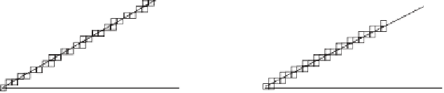
2. However, in our age of
computers and computer-aided design, virtually all graphics output devices (monitors,
plotters, and printers) use a raster scan and are based on pixels. A line is drawn as a
set of individual pixels, and even a little experience with such lines shows that a line
at 30
◦
to the horizontal looks bad. Much better results are obtained when drawing a
line at about 27
◦
because the tangent of this angle is 0.5, resulting in a line made of
identical sets of pixels (Figure 2.9).
30
0
27
0
Figure 2.9: Pixels for
30
◦
and
27
◦
Lines.


Search WWH ::

Custom Search