Graphics Programs Reference
In-Depth Information
The rotation matrix is obtained from Equation (1.32)
⎛
⎞
e
2
+
f
−
f
3
−
e
2
f
1
−f
2
−
ed
1+
f
d
0
⎝
⎠
d
2
+
f
−
f
3
−
d
2
f
1
−f
2
−
ed
1+
f
e
0
T
2
=
.
(3.11)
−
d
−
e
f
0
0
0
0
1
The two other tasks are to translate the viewer from the origin to point (0
,
0
,
−
k
)
by means of
T
3
and to use matrix
T
p
to project from the standard position:
⎛
⎝
⎞
⎠
⎛
⎝
⎞
⎠
1000
0100
0010
00
1000
0100
000
r
0001
T
3
=
,
T
p
=
.
(3.12)
−
k
1
The result is the matrix product
T
g
=
T
1
T
2
T
3
T
p
(3.13)
⎡
⎣
⎤
⎦
e
2
+
f
+
f
2
1+
f
−
de
1+
f
0
dr
d
2
+
f
+
f
2
1+
f
−
de
1+
f
0
er
=
.
−
d
−
e
0
fr
cd
+
bde
−
ae
2
−
af
+
cdf
−
af
2
1+
f
−
bd
2
+
ce
+
ade
−
bf
+
cef
−
bf
2
1+
f
0
−
(
ad
+
be
+
cf
)
r
For the special case of a viewer located at
B
=(
−
k
sin
θ,
0
,
−
k
cos
θ
)=(
−
kα,
0
,
−
kβ
)
and looking in direction
D
=(
α,
0
,β
), this reduces to matrix (3.9).
y
(
−
1,1,0)
y
z
z
2
k
x
x
(a)
(b)
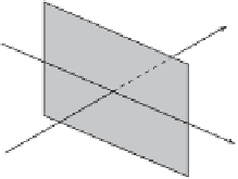
Figure 3.33: Two Tests of Matrix
T
g
.
Matrix
T
g
is now tested twice. The first test (Figure 3.33a) assumes that the
viewer is at the standard location (0
,
0
,
1
,
1
,k
). (These
components still have to be normalized.) We compute the projection of point (
−
k
) but looking in direction (
−
−
1
,
1
,
0)


Search WWH ::

Custom Search