Biology Reference
In-Depth Information
A
B
120
40
0
20
40
60
Contour length (
μ
m)
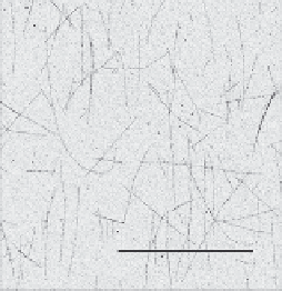
FIGURE 6.3
Determination of MT contour length. (A) The distribution of MT lengths is determined by
attaching individual MTs to a coverslip, visualizing them using confocal microscopy,
and measuring their lengths manually using built-in measurement tools in ImageJ. Under our
polymerization conditions, we find the length distribution is independent of tubulin
concentration. The mean length measured from MTs assembled using 50
m
M tubulin is
23.3
m (SEM; 710 measurements), as shown. (B) Sample image for the length
measurement (scale bar is 50
0.4
m
m; note that image has been adjusted to enhance contrast
and brightness prior to printing).
Adapted from
Yang et al. (2012)
. Reproduced by permission of The Royal Society of Chemistry.
m
0.1 mm
3
)
using two strips of double-sided tape that attach a clean coverslip to a clean glass
slide. Prior to introducing the MT solution, we flow in 20
preserve MT lengths. We form a microscope flow chamber (
25
4
L of 0.2 mg/mL strepta-
vidin (SA20; Prozyme), incubate 5 min, flow through 100
m
m
L of G-PEM80 with
100
L of diluted
MT solution. To minimize photobleaching, we frequently supplement the MT solu-
tion with an oxygen scavenging system (glucose, glucose oxidase, and catalase).
After a 10-min incubation period during which time nearly all MTs attach to the
coverslip, we visualize the surface-bound MTs using Total Internal Reflection
Fluorescence (TIRF) or confocal microscopy and measure their lengths manually
using built-in measurement tools in ImageJ (
Fig. 6.3
;
Yang et al., 2012
).
m
M taxol to remove any unbound streptavidin, and then flow in 30
m
6.1.3
Magnetic tweezers devices for microscale manipulation
6.1.3.1
Principles of magnetic tweezers technologies
Mechanical measurements are performed using a custom-built magnetic tweezers
system that enables precise manipulation of magnetic beads along the optical axis
(the
z
-axis) and simultaneous three-dimensional tracking of bead position (
Kim &
Saleh, 2008; Manosas et al., 2010; Ribeck & Saleh, 2008
). A simple inverted micro-
scope is constructed using an oil-immersion objective, typically 100
, 1.25 NA, to
visualize an appropriate field of view around the magnetic particle (
Fig. 6.4
). The