Biomedical Engineering Reference
In-Depth Information
R1
R3
R
R
C2
2C
OUTPUT
INPUT
R2
0.5R
C1
C3
C
C
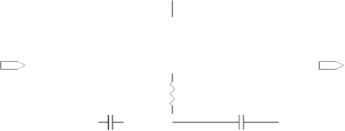
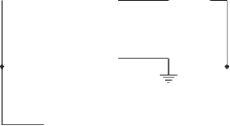
Figure 2.18
The notch frequency of the simple twin-T filter is
f
notch
1/2π(R1)(C1) if C1
C3, C2
2C1, R1
R3, and R2
R1/2.
However, the use of precise and tightly matched components is extremely important to yield a deep notch at the required frequency.
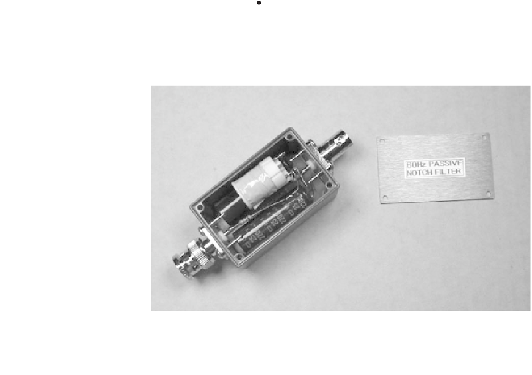
Figure 2.19
Passive notch filters can be built into small enclosures with BNC connectors on each
end and placed between equipment stages.
the output load. The circuit of Figure 2.20 shows how a unity-gain follower bootstraps the
network in an active twin-T notch
filter. Since output of the op-amp presents a very low
impedance, the notch frequency and depth are not changed. However, the
Q
value of the
fi
fi
filter increases proportionately to the level of signal that is fed back to the junction of R2
and C2 (the point that is grounded in a passive twin-T notch
fi
filter).
filter power line interference. The power
line frequency in many countries deviates quite a bit from the nominal 50 or 60 Hz. A sec-
ond op-amp can be added as shown in Figure 2.21 to control the
Q
value of the
A very high
Q
value is not always desirable to
fi
filter. Here,
the amount of feedback that is provided to the R2/C2 junction is set by potentiometer R4.
An op-amp is needed to bu
fi
er the feedback signal to ensure a constant low impedance at
the R2/C2 junction so that the notch frequency and depth do not change as a function of
the potentiometer setting.
ff


Search WWH ::

Custom Search