Biomedical Engineering Reference
In-Depth Information
Attenuation (dB)
Phase (deg.)
10
0
Magnitude:
Chebyshev
0
-10
-20
-100
-30
Butterworth
-40
Bessel
-200
-50
Phase:
Chebyshev
-60
-70
-300
Butterworth
-80
Bessel
-90
-400
-100
10
100
1000
Frequency (Hz)
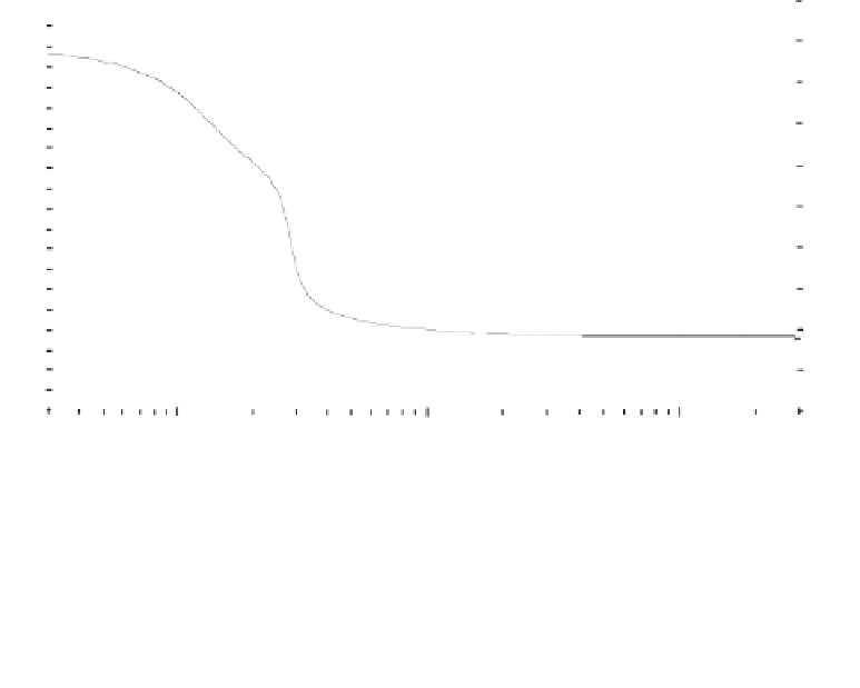
Figure 2.13
Real-world filters do not yield a perfect step in the frequency domain. Some of the most
common filter responses are the Butterworth, Chebyshev, and Bessel. Each of these filter responses
has advantages and disadvantages, and it is the designer's task to find a suitable compromise that best
fits the task at hand from phase- and amplitude-response graphs such as this one for fourth-order filters
with a
3-dB cutoff frequency of 30 Hz.
1. Sallen-Key topology
(also known as the
voltage-controlled voltage-source topology
)
uses an op-amp as a gain block. Because of this, the Sallen-Key con
fi
guration is relatively
independent of op-amp speci
fi
cations and requires the op-amp's bandwidth only to extend
slightly beyond the
filter stopband frequency. The Sallen-Key topology features good
phase response, but its frequency response and
Q
are sensitive to the gain setting.
2. Multiple-feedback topology
uses op-amps as integrators that need a minimum loop
gain of 20 dB (open-loop gain 10 times the closed-loop gain) to avoid
Q enhancement
, mak-
ing it di
fi
cult to get high-
Q
performance. However, this
fi
filter con
fi
guration is relatively
insensitive to passive-component values.
3. State-variable topology
uses op-amps as ampli
ers and integrators, which again need
a minimum loop gain of 20 dB. In addition, the op-amps need a frequency response that is
fl
fi
flat to beyond the stopband frequency. Despite this, state-variable
fi
filters provide inde-
pendent control over gain, cutoff
frequency,
Q
, and other parameters but require more pas-
sive components. A very nice feature of this topology is that the same circuit yields
low-pass, high-pass, and bandpass response.
4. Impedance-converter topology
(also known as
frequency-dependent negative-resistance
topology) requires op-amps with a minimum loop gain of 20 dB at the resonant negative
resistance frequency. Multiple op-amps are needed, and use of dual-packaged devices is rec-
ommended for matched performance in each leg. FET-input op-amps are used because of
their low bias currents. Although the impedance-converter approach requires more compo-
nents, it is relatively insensitive to variations in their values.
ff
filtering applications commonly have bandwidths limited to the
audio range, the biggest trade-off
Since biopotential signal
fi
ff
is often the number of op-amps versus the level of control
that a designer has over the
fi
filter. For a person inexperienced with the design of active
fi
filters,


Search WWH ::

Custom Search