Biomedical Engineering Reference
In-Depth Information
6.
Typical peak-to-peak noise measurements are found by reading the maximum
peak-to-peak voltage noise of the circuit's output for three observation periods of
10 seconds each, then dividing by the gain of the ampli
fi
er (i.e., 100,000).
er
described in the earlier project. Use a procedure similar to the one used earlier to measure
the CMR of the instrumentation biopotential ampli
You may want to compare the CMR of the ICIA to that of the di
ff
erential ampli
fi
fi
er:
erential inputs as shown in Figure 1.24.
2.
Adjust the signal generator to produce a 60-Hz, 5-V
p-p
input signal
V
in CM
.
3.
Measure the corresponding common-mode output voltage
V
out CM
.
4.
Calculate the common-mode gain
G
CM
1.
Connect the equipment, shorting the di
ff
V
out CM
/
V
in CM
.
Using the measured gain of the biopotential ampli
fi
er, calculate the common-mode
rejection:
G
d
G
i
ff
e
C
ential
r
CMR(dB)
20 log
10
M
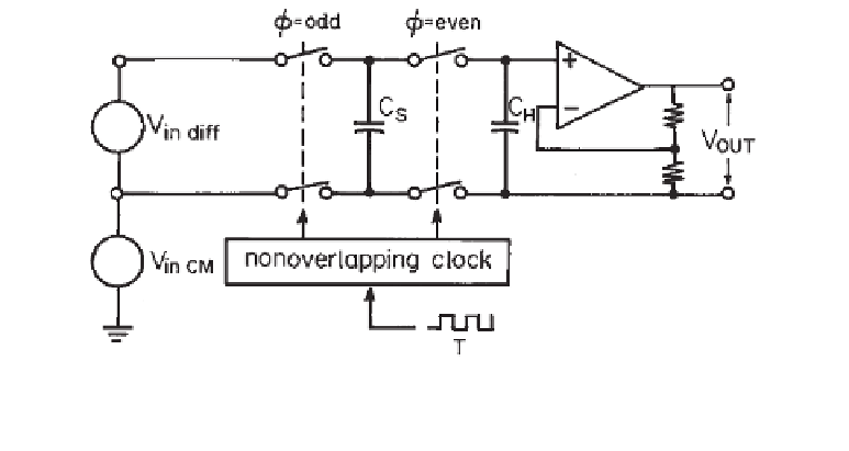
Switched-Capacitor Instrumentation Biopotential Amplifier
Di
erential biopotential signal recordings can be done through circuits other than classi-
cal op-amp di
ff
ff
erential or instrumentation ampli
fi
ers. The simpli
fi
ed circuit in Figure 1.29
implements a simple but precise instrumentation ampli
fi
er that uses a switched-capacitor
building block. It converts di
ff
erential signals from a preampli
fi
ed electrode pair to a sin-
gle-ended output while rejecting common-mode signals in an e
ective manner. In this cir-
cuit, a solid-state dual-pole dual-throw (DPDT) switch block converts the di
ff
ff
erential input
to a ground-referred single-ended signal which may then be ampli
fi
ed by a noninverting
follower op-amp con
guration.
During the time that the input switches are closed (
fi
odd), sampling capacitor C
S
acquires the input signal
V
in diff
. When the input switches open (
Φ
Φ
even), hold capacitor
C
H
receives the sampled charge. Switching C
S
continuously between the input
Figure 1.29
In this switched-capacitor instrumentation amplifier, a solid-state DPDT switch block
converts the differential input to a ground-referred single-ended signal which is then amplified by a
noninverting follower operational amplifier configuration.


Search WWH ::

Custom Search