Biomedical Engineering Reference
In-Depth Information
UltraVolt, Model No: IC24-P30,
Programmable High Voltage Power
Supply
IC37
J11
1
3
5
7
8
1
2
3
4
5
6
7
11
Power Return
Power In
I - Sense
Enable
Signal Gnd
Remote Adj.
+5V Ref.
HV Output 2
10
HV Output 1
9
HV Return 2
8
HV Return 1
UltraVolt IC24-P30
J15
2
High
Voltage
Out
Dummy
Load
Charge Dump
R82
400K
R84
1M, 500V
R83
100 Ohm, 10 Watt
R107
100 Ohm, 10 Watt
C63
250uF, 360V
4V@1000 Vin
R108
1M, 500V
R85
D8
LED
2
V_Ca p_Out
IC38
R87
100
8
7
6
5
C
D14
5.1V
Out 1-
Out 1+
Out 2-
Out 2+
Q35
LS1
2
3
Anode
Cathode
R86
8K
C64
250uF, 360V
R88
1
G
Alarm
PVI1050
IXGH17NU1
E
J13
2
4
I_Cap_Out
1
R89
10M
+5V
Q42
BS170
R90
0.5 Ohm
3
GND
2
Enable
Disable
3
D10
1N4148
IC39
HV Gnd
8
7
6
5
R91
100
Out 1-
Out 1+
Out 2-
Out 2+
2
3
Anode
Cathode
1
Q36
BS170
2
PVI1050
1
Q43
BS170
3
R92
470K
2
3
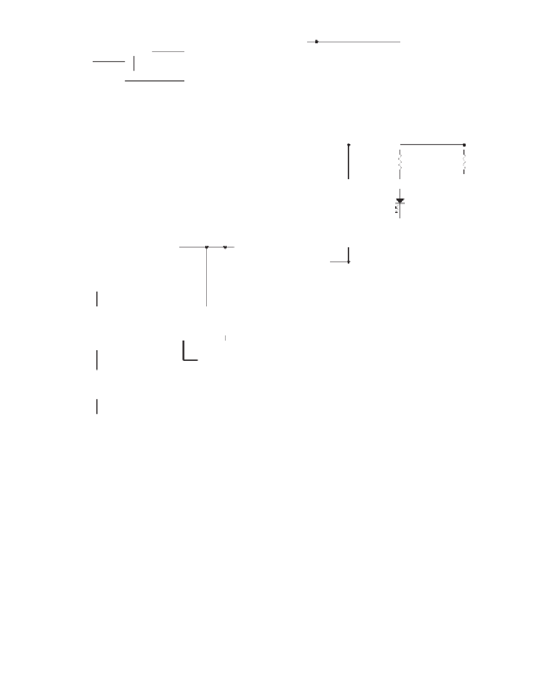
Figure 8.38
Photoflash electrolytic capacitors are the most commonly used capacitors in implantable defibrillators. Two Panasonic TS-HB-
series 330-µF capacitors at 450 V are used in the shock box for an equivalent capacitance of 165 µF at 900 V. The capacitors are charged in series
directly from a programmable HV power supply. 400-kΩ bleeder resistors equalize the voltage across the capacitors during charging. A blink-
ing LED and a piezo buzzer are powered directly from the HV line to warn the user of the presence of high voltage in the capacitor bank.
load (
C
L
) to 99% of the desired value:
C
L
I
sho
C
F)
t
(
)
i
(
n
A
T
(ms)
V
rt
where
C
L
30 mA. As such, the
worst-case charge time is just over 4 s (as long as the necessary power is available at the
supply input).
165
µ
F,
C
int
0.018
µ
F,
V
820 V (for ~50 J), and
I
short
Energy Storage Capacitor
Photo
fl
ash electrolytic capacitors are the most commonly used capacitors in implantable
de
fi
brillators. These capacitors have been tested thoroughly in the photo
fl
ash and strobe


Search WWH ::

Custom Search