Biomedical Engineering Reference
In-Depth Information
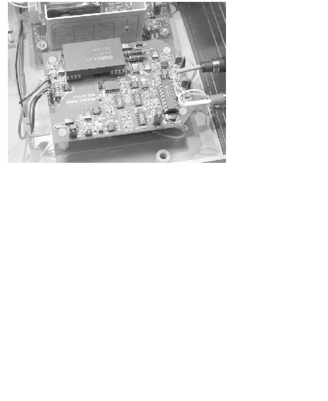
Figure 8.24
This sensor circuit generates low-energy capacitive-discharge pulses to measure two-
terminal impedance across electrodes implanted in the heart. An ISO107 isolation amplifier is used
for galvanic isolation of the applied part from external signal acquisition equipment.
switches are open during the charging of
C
a
1
and
C
a
2
. This is the normal state of the state
machine implemented by the microcontroller (IC12) of Figure 8.26.
When an impedance measurement is to be performed, the external data acquisition sys-
tem generates an interrupt that is received through line IMPED_START on the state-
machine microcontroller IC12. Switches IC9D, IC9C, and IC9A are opened. Almost
simultaneously, IC10C connects the reference terminal of the capacitors to one of the
leads. Then, the other lead is connected to
C
a
1
through IC10D and dc-blocking capacitor
C48. The discharge of
C
a
1
through the body-lead system is sampled for 10
µ
s. IC10D is
then opened, and
C
a
2
is allowed to discharge through the lead system for 10
µ
s by way of
IC10A, C48, and IC10C.
After the samples are taken, IC10C is opened to
float the lead system in relationship to
the system ground. (Optionally, IC10B is closed to discharge the dc-blocking capacitor
actively for 768
fl
s. This was left in the circuit to make it possible to implement CCD
measurements.) IC9C is closed and the di
µ
erential signal corresponding to the compen-
sated impedance measurement is developed by IC8A, IC8D (unity-gain bu
ff
ff
ers, used only
to preserve the charge on the active capacitors), and instrumentation ampli
fi
er IC11. At the
end of 768
s, the sample-and-hold implemented through IC9B, C44, and IC8B holds the
voltage level corresponding to the impedance measurement. This level is then scaled and
fi
µ
filtered through IC8C and its associated components.
The circuit of Figure 8.27 isolates sensor signals from recording instruments connected
to the sensor. This circuit also generates isolated power for the applied part of the intra-
cardiac impedance sensor. With the component values shown, the circuit produces an out-
put voltage as a function of impedance (resistance) as shown in the graph of Figure 8.28.
It should be noted that other implementations of the same circuit, which are particularly
e
cient for use in implantable medical devices, are possible, as shown in Figure 8.29.

Search WWH ::

Custom Search