Biomedical Engineering Reference
In-Depth Information
Rlead
V
src
CH
S1
RHP
RHs
S3
+
Rionic
Ca
Cdc_block
OUT
Rtissue
(Cardiac, etc)
S/H
LEAD
Cp
S5
Rpass
-
S4
V
iegm
HEART
S/H
S2
V
noise
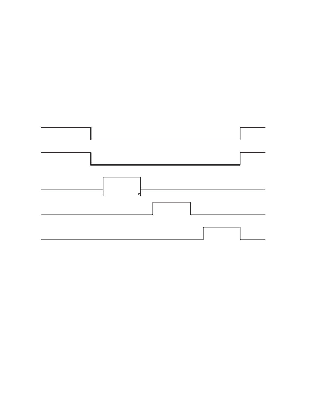
Switch Closed
S1
Switch Open
S2
Switch Closed
S3
Switch Open
T
CCD =
10
µ
s
S4
T
CCD = 10
µ
s
S5
Sample
S/H
Hold
Figure 8.22
The CCD impedance sensor for implantable cardiac stimulators: (
a
) simplified circuit diagram of the sensor; (
b
) simplified
timing diagram. At the beginning of each measurement cycle,
C
a
is charged to
V
src
while
C
p
is discharged.
C
p
is then connected to the body,
allowing it to sample the potential across the lead system for a brief interval
t
CCD
. Immediately thereafter,
C
a
is discharged across the lead
system for the same amount of time
t
CCD
. The subtraction of
V
C
p
from
V
C
a
is a value proportional to the tissue impedance,
t
CCD
C
a
ln{[
V
C
a
(
t
CCD
)
R
V
C
p
(
t
CCD
)]/
V
src
}
In reality, however, other sources in the circuit (e.g., intrinsic electrical activity of the heart,
electrode polarization potentials) have a strong e
ff
ect on
V
C
a
(
t
) and make the measurement
of
R
imprecise.
By using the voltage sampled in
C
p
, the e
ects of these sources of error can be canceled.
This compensation process is carried out by subtracting
V
C
p
from
V
C
a
before determining
the resistive component
R
of the impedance:
ff
t
C
a
ln{[
V
C
a
(
t
)
R
V
C
p
(
t
)]/
V
src
}


Search WWH ::

Custom Search