Biomedical Engineering Reference
In-Depth Information
R66
20K 1%
R68
R69
R67
20K 1%
10K 1%
20K 1%
-5Viso
C63
.01uF
D8
1N4148
IC14A
TL082
Absolute-Value
Out
4
IC14B
TL082
R70
I
4
2
-
VTOI_1
JP19
1
2
1
6
-
20K 1%
3
7
+
5
+
8
D9
1N4148
R71
15K
8
R72
6.2K
C64
+5 Viso
.01uF
I
I
I
I
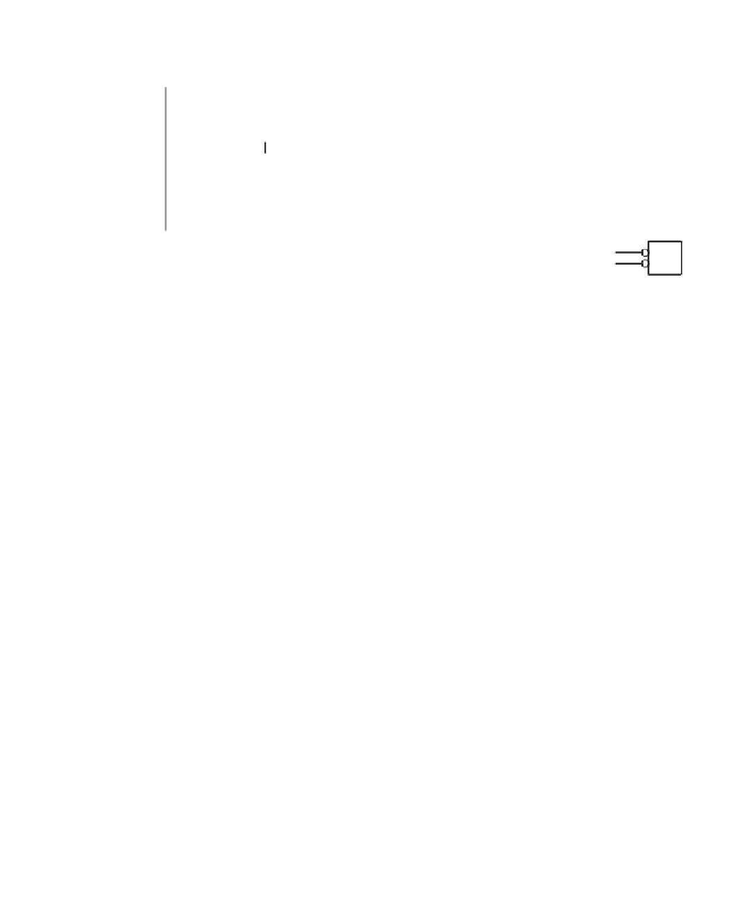
Figure 8.20
A precision full-wave rectifier built around IC14A is available for testing the general-purpose impedance plethysmograph. It
provides the absolute value of the voltage generated by the current source across the current-injection electrodes.
ejection, relaxation, and passive
filling) and allow estimation of the heart's contractile state
(inotropy). Areas under the PV loop are related to cardiac work, and thus heart e
fi
ciency
can also be calculated. Finally, the shape of the PV loop can be analyzed to assess valvu-
lar function as well as the coupling between the ventricles and the arterial load.
INTRACARDIAC IMPEDANCE SENSOR
Impedance sensors for use as hemodynamic sensors in implantable pacemakers don't need
to be as accurate as those used for the generation of PV loops. Relative rather than absolute
indications of volumes are usually su
cient. As such, impedance sensors used in pace-
makers often make certain assumptions that simplify the volume-estimation problem at the
expense of precision. The circuit represented in Figure 8.22 is a simple, yet highly e
ective
impedance sensor suitable for implantable cardiac stimulators. This technique is known as
compensated capacitor discharge
(CCD)
impedance
sensing [Prutchi, 1996]. It makes use
of very small energy probe pulses (orders of magnitude subthreshold) to estimate the resis-
tive component of the lead impedance. The output of the circuit is an analog voltage pro-
portional to the lead impedance.
In its simplest form, the circuit comprises a
ff
F), referred
to as the
active capacitor
. At the beginning of each impedance measurement cycle,
C
a
is
charged to a preselected voltage level
V
src
(e.g.,
fi
first capacitor,
C
a
(e.g., 0.01
µ
1 V). At the same time, a capacitor
C
p
(of the same value as
C
a
), referred to as the
passive capacitor
or
presample capacitor
,is
discharged to 0 V. After
C
a
is fully charged to
V
src
and
C
p
is fully discharged, a switch con-
nects
C
p
to the body, allowing it to sample the potential across the lead system and a
dc-blocking capacitor
C
b
(e.g., 1
µ
F) for a brief interval
t
CCD
(e.g., 10
µ
s). The voltage


Search WWH ::

Custom Search