Biomedical Engineering Reference
In-Depth Information
Figure 1.21 presents a di
ff
erential ampli
fi
er based on a single op-amp. If R1
R2 and
R3
R4, the gain of the stage is given by
R
R
3
2
R
R
4
1
G
In this case, the transfer function is
R
R
4
1
V
out
V
in
or
R
R
3
2
V
out
V
in
where
V
1
V
2
is the di
ff
erential voltage
V
in
.
er is critical to preserve the property of an ideal op-
amp by which its common-mode rejection ratio is in
The balance of a di
ff
erential ampli
fi
V
2
, an output voltage of
zero should be obtained, disregarding any common-mode voltage
V
CM
. If the resistor equal-
ities R1
fi
nite. If
V
1
R4 are not preserved, the common-mode rejection deteriorates.
The main problem regarding use of a simple di
R2 and R3
ff
erential ampli
fi
er as a biopotential
ampli
fi
er is its low input impedance. Especially in older equipment,
where this
con
erential biopotentials, high-input-impedance JFET
transistors or MOSFET-input op-amp unity-gain voltage followers were used to bu
fi
guration was used to amplify di
ff
ff
er
each input of the di
ff
erential ampli
fi
er. Despite the enhanced CMR of the di
ff
erential
ampli
guration over that of a single-ended system, use of a BPD circuit can
increase considerably the CMR of di
fi
er con
fi
ers. This is especially
true regarding the rejection of interfering signals with high-frequency components.
ff
erential biopotential ampli
fi
C1
0.1uF
R4
10M
-9V
+9V
R1
10K
IC1
TL081
C2
1uF
4 5
IC2
TL0
81
7
1
2
-
+
6
3
2
J1
Input
+
3
6
1
-
R2
10K
BNC
7 1
2
R5
1M
R6
1M
4
5
C3
0.47uF
R3
10M
+9V
-9V
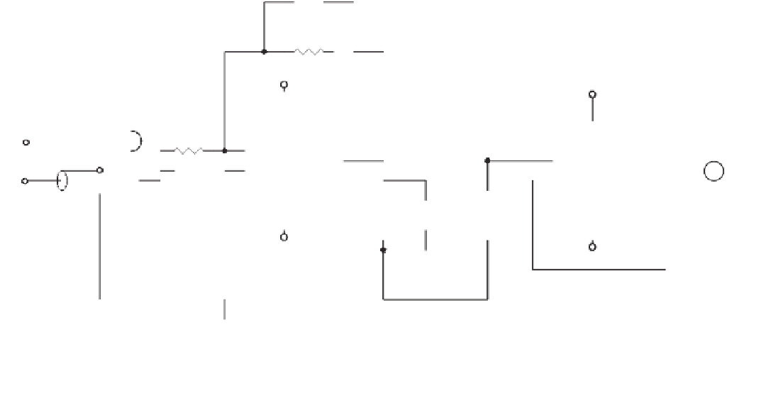
Figure 1.22
In this simple differential biopotential amplifier, signals originating from electrophysiological activity in the body are detected
by measuring the potential differences between electrodes connected to the inputs. If the sensing bioelectrodes are placed in the proximity
of the biopotential source, common-mode electrical interference affects both probes more or less equally and are rejected by the differential
amplifier stage.


Search WWH ::

Custom Search