Biomedical Engineering Reference
In-Depth Information
Oscillator
Voltage Doubler
R6
10k
Q2
2N3906
R1
4.7M
R9
10k
C1
0.47uF
Q1
R8
50k
R5
50k
R3
20k
MPS2924
+
C2
22uF
Q4
D1
1N4148
Q3
MPS2924
V1
2.8V
+
C2
22uF
MPS2924
Cathode
Electrode
D2
1N4148
R4
10k
R7
10k
R_HEART
1k
R2
1.8k
Anode
Electrode
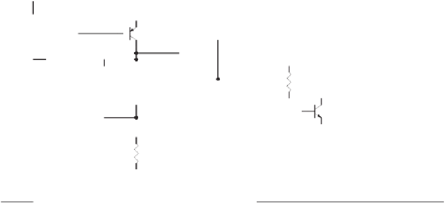
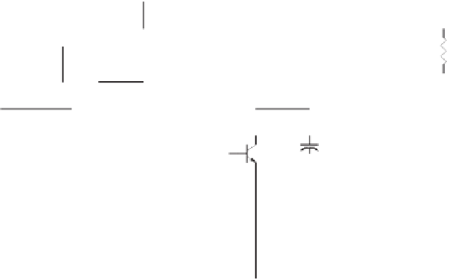
Figure 8.3
Early pacemakers had a period and pacing pulse characteristics (amplitude, waveshape, and duration) that were solely a func-
tion of their circuit. In this replica of a 1960s design by Wilson Greatbatch, a self-staring blocking oscillator drives a voltage doubler to pro-
duce pacing pulses with waveshape parameters (pulse width and interval between pulses) that remains almost constant despite drops in
battery voltage.
batteries of 1.35 V and leads connecting the unit to the ventricle. The output was a 2-ms pulse
of 5 to 8 V in amplitude every 1 s. Later, Greatbatch adopted the lithium-iodide battery
chemistry, powering his circuits from a single 2.8-V cell. In the circuit of Figure 8.3, the out-
put of the blocking oscillator drives a voltage doubler, making the pacing pulses delivered to
the heart achieve su
ciently high amplitudes (approximately 5 V, as shown in the simulation
results of Figure 8.4) for the pacing electrodes of the time to “capture” the heart.
Early pacemakers did not consider that the patient's heart could have spontaneous elec-
trical activity. An important development in the
field of cardiac pacing was the inclusion
of circuitry that could detect the patient's intrinsic heart activity and pace only when the
heart's rate fell below a prede
fi
ned rate. Figure 8.5 shows that the logic needed to account
for the patient's intrinsic activity simply requires the addition of a sense event to the state
machine. When the pacemaker detects an intrinsic cardiac event, the timer in charge of
issuing [Time Out] is retriggered.
In reality, however, the implementation of such a state machine is not all that simple,
since it requires the inclusion of an ampli
fi
er and associated circuitry capable of detecting
the heart's intrinsic activity. Since pacemaker sensing circuits usually limit their complex-
ity to a low-power biopotential ampli
fi
er followed by a threshold detector, they detect
intrinsic cardiac events based on the presence of a signal that surpasses the threshold volt-
age. This means that as the depolarization waveform sweeps past the pacing electrodes, the
sense ampli
fi
er does not yield a single sharp transition that can be translated into a clear
[Sense] event. Rather, it behaves as a very “bouncy” switch that generates a pulse train
with unpredictable transitions and lasts as long as the cardiac signal remains within the
range of the threshold comparator. In a similar way, the pacemaker's logic must be able to
discriminate between an intrinsic beat and potentials resulting from pacing (the pacing
fi


Search WWH ::

Custom Search