Biomedical Engineering Reference
In-Depth Information
12V
B1-B4
Duracell DL2032 x 4
IC1
NE555
IC2
ICM7555
7
3
R3
2K
DSCHG
OUT
Q1
BC337
R5
5
5
3
CV
CONTV
OUT
4
RST
12K
6
7
J1
THR
DISCH
D2
1N4148
C5
2
D1
1N4148
TRG
4
2
6
1
RES
ET
TRIG
THOLD
8
R4
1K
VCC
0.22uF
R1
15M
R2
39K
1
8
R6
22K
V+
Electrodes
C3
10nF
1
C1
10nF
+
C2
22uF
+
C4
1uF
J2
1
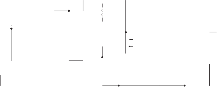
Figure 7.8
A variation on the capacitor-discharge circuit is the capacitor-coupled stimulator. In this circuit for the stimulation of denervated
muscles, C5 differentiates the rectangular square waveform at the output of Q1 to yield a net-zero charge transfer across the tissue.
by delivering the energy stored in this capacitor through the tissue. A zero net current
ow
through the tissue results from passing the same amount of charge (albeit not within the
same amount of time) through the tissue during the discharge phase as was delivered dur-
ing the stimulus pulse, but in the opposite direction. Not doing so would cause electro-
chemical imbalance, which can result in electrode corrosion and tissue damage. Taking the
ACTIVE DISCHARGE line low closes Q1, allowing the charge in coupling capacitor C1
to
fl
). Any
remaining charge after the fast discharge time is delivered at a slower rate through R1
(100 k
fl
flow through the tissue via resistors R2 and R1 (100
Ω
in parallel with 100 k
Ω
). With the component values shown, this circuit is suitable for delivering stimulus
pulses with durations of up to 2 ms into implanted electrodes that present a load impedance
of approximately 500
Ω
.
A variation on the capacitor-discharge circuit is the capacitor-coupled stimulator.
Figure 7.8 shows a stimulator based on the circuit con
Ω
guration proposed by Sebille et al.
[1988] for the stimulation of denervated muscles. In this circuit, timer IC2 generates a
square wave that drives transistor Q1. The common-collector connection allows the output
voltage to remain independent of the impedance presented by the tissue being stimulated.
C5 di
fi
erentiates the rectangular square wave to yield a zero net charge transfer across the
tissue. Timer IC1 cycles IC2's power on and off,
ff
, making it possible to vary the stimulation
duty cycle by changing the values of R1 and R2.
ff
Current-Source Stimulators
Hochmair [1980] described a CMOS low-power current source suitable for implantable
devices. It uses a standard CMOS 4007 integrated circuit, which contains six enhancement
MOSFETs, three n-channel and three p-channel. The n-channel bodies (p-silicon) are con-
nected to pin 7 and must be kept at the most negative voltage used in the circuit. The
p-channel bodies (n-silicon) are connected to pin 14 and must be kept at the most positive
voltage used in the IC. The transistor elements are accessible through the package terminals.


Search WWH ::

Custom Search