Biomedical Engineering Reference
In-Depth Information
For the example, when the cutoff
ff
should be around 300 Hz, which requires that
f
clock
30 kHz, obtained with C11
120 pF, a series resistor (R18) can be added to trim the oscil-
lation frequency. In this case, the new clock frequency is given by
0
1
f
clock
R18
f
clock
4 (R18)(C11)
f
clock
R18
0
where
f
clock
0
is the oscillator frequency when R18 is not present (obtained through the
prior equation). After
R18
set from the pre-
ceding stages is compensated with IC1A by setting R3. Finally, the
RC
low-pass
fi
filtering, the gain is adjusted through R10 and all o
ff
fi
lter
formed by R5 and C6 removes any switching noise introduced by IC3.
The stability of the PLL circuit depends on the stability of the frequency-setting compo-
nents. Proper performance requires the use of low-temperature-coe
cient high-tolerance
components. Resistors should be precision 1% tolerance type of the RN60D variety.
Capacitors should be Mylar, polyester
film, or other types that remain stable with age and
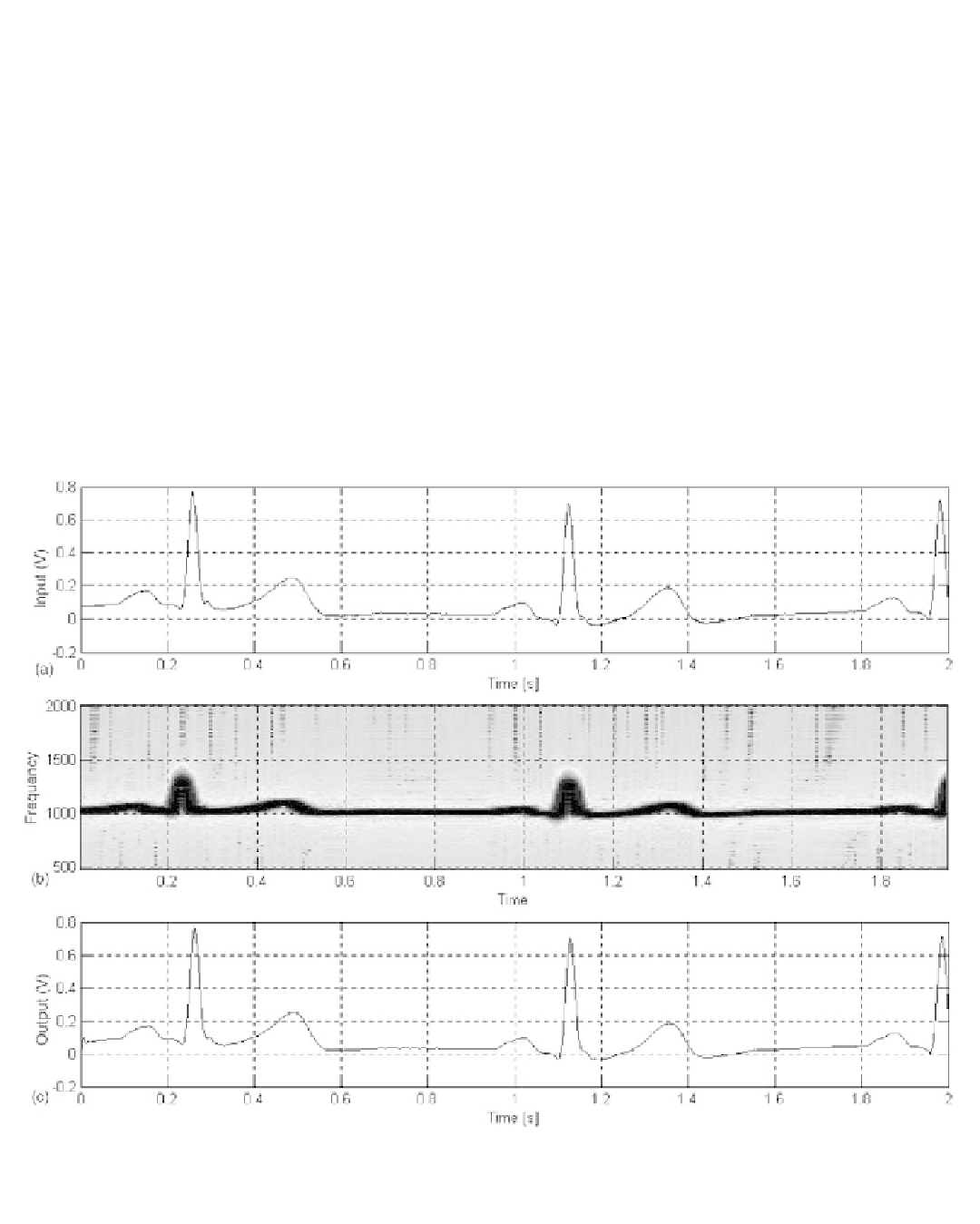
which are not sensitive to temperature variations. Figure 6.19 demonstrates the perform-
ance of the technique. The test signal is a real ECG that was digitized at a sampling rate
of 5 kHz with 12-bit resolution. Figure 6.19
b
shows the spectrum of the FM signal, and
fi
Figure 6.19
A real ECG signal that was digitized at a sampling rate of 5 kHz (a) is used to frequency-modulate a 2-kHz carrier using the
Matlab vco.m function (b). The output of the PLL-based FM demodulator is shown in part (c), showing how the demodulated signal faith-
fully reproduces the dc offset and low-frequency components of the ECG.

Search WWH ::

Custom Search