Biomedical Engineering Reference
In-Depth Information
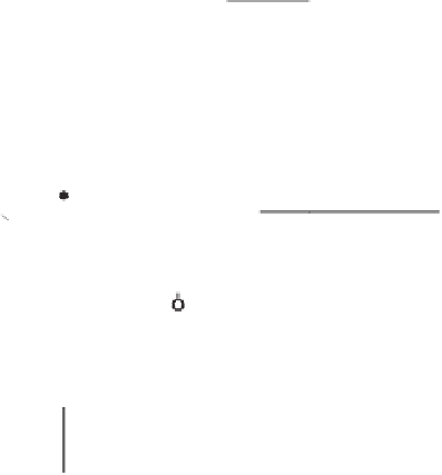
Rf
If
-VCC
A
Rin
-
Iin
+
Vin
Vout
+VCC
Figure 1.4
Inverting voltage amplifier.
Therefore, by substitution and by solving for
V
out
,
R
R
f
V
in
in
V
out
This equation can be rewritten as
V
out
GV
in
where
G
represents the voltage gain constant
R
f
/
R
in
.
The circuit presented in Figure 1.5 is a noninverting voltage ampli
er, also known as a
noninverting follower
, which can be analyzed in a similar manner. The setting of the nonin-
verting input at input voltage
V
in
will force the same potential at point
A
. Thus,
fi
V
R
i
i
n
n
i
in
and
V
out
R
f
V
in
i
f
But in the noninverting ampli
fi
er
i
in
i
out
, so by replacing and solving for
V
out
, we obtain
R
f
n
V
out
1
R
V
in
i
The voltage gain in this case is
R
f
n
G
1
R
i
A special case of this con
fi
guration is shown in Figure 1.6. Here
R
f
0, and
R
in
is unnec-
essary, which leads to a resistance ratio
R
f
/
R
in
0, which in turn results in unity gain.
er
or
voltage follower
, is often used in bio-
medical instrumentation to couple a high-impedance signal source, through the (almost)
in
This con
fi
guration, termed a
unity-gain bu
ff
nite input impedance of the op-amp, to a low-impedance processing circuit con-
nected to the very low impedance output of the op-amp.
fi


Search WWH ::

Custom Search