Biomedical Engineering Reference
In-Depth Information
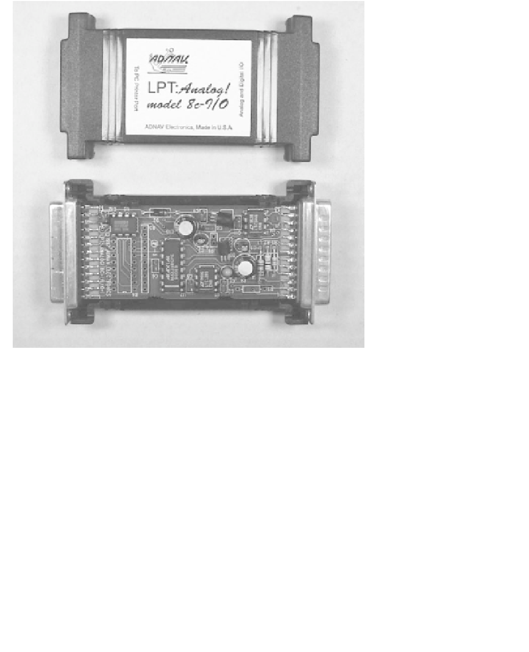
Figure 5.1
The universal sensor interface is a simple device that plugs into the printer port of the
PC. It can excite, control, and read a wide variety of sensors directly from a PC.
Unlike ordinary data acquisition setups, the universal sensor interface o
ff
ers a great
degree of
flexibility and portability. Virtually all PCs come equipped with a parallel printer
port, and reconnecting this data acquisition system to the computer typically does not
require delving into the enclosure. Moreover, since the use of the printer port is standard-
ized, the same software will run on any PC without the need for recon
fl
guration. As long
as the signals to be converted are correctly scaled and sampled, the universal sensor inter-
face should have you experimenting with the new generation of sensors in no time at all.
fi
A/D Converter
As shown in Figure 5.3, a Linear Technology LTC1285 integrated circuit (IC1) is at the
heart of the A/D circuitry within the universal sensor interface. This IC implements a 12-
bit successive-approximation A/D converter, complete with a sample-and-hold and a high-
speed three-wire serial interface. A 2.5-V reference voltage is regulated by D1 and
supplied to the VREF input of the A/D converter.
The serial interface to the LTC1285 requires only three digital lines. Data-conversion ini-
tiation and data-read operations are controlled by the *CS (chip select) and SCLK (serial
clock) lines. Data are obtained serially through the DOUT line. As shown in Figure 5.4
a
,
an A/D conversion is initiated by a falling edge on the *CS line. At this point, the sample-
and-hold stores the input voltage and the successive-approximation process commences.

Search WWH ::

Custom Search