Biomedical Engineering Reference
In-Depth Information
C34
470uF
+
IC10
LM317HV/ TO
D4
D5
D6
48V
1
2
1
2
1
2
3
2
+32V
VIN
VOUT
1N4005
1N4005
1N4005
+
C33
470uF
R30
82
+
C35
470uF
1
C36
0.1uF
C39
C38
0.1uF
+
R39
50k
100uF
C37
0.01uF
IC11
LM7812C/ TO220
T1
12VAC 1A
D7
1
2
1
3
+12V
IN
OUT
115VAC
1N4005
+
C
40
2200uF
+
C
43
100uF
C41
0.1uF
C42
0.1uF
2
IC12
LM78L05A/ TO39
1
2
+5V
VIN
VOUT
+
C47
100uF
C46
0.01uF
+
C48
100uF
C44
100uF
+
C45
0.01uF
3
IC13
LM7912C/TO3
D8
2
1
3
2
IN
OUT
-12V
1N4005
C52
100uF
C49
C51
0.1uF
C50
0.1uF
+
+
1
2200uF
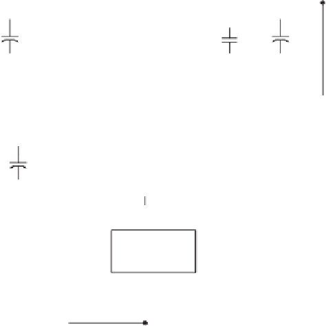
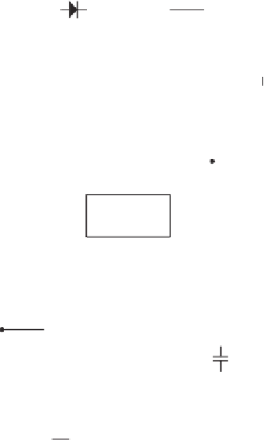
Figure 4.12
Dc power for the various circuits of the spectrum analyzer is derived from a single 12-V ac input. A voltage of
12 V pow-
ers most of the circuitry, including the up-converter, tuner, and sawtooth generator;
5 V powers the IF processor. Sweeping the tuner across
its 450 to 850 MHz range requires up to
32 V to drive its varactors. A voltage of
12 V is used as bias to ensure that sweeping can be
accomplished within any desired portion of the full range.
CONDUCTED EMISSIONS
Conducted emissions measurements are made to determine the line-to-ground radio noise
from each power-input terminal of a line-powered medical device. Measurements are
taken using a line impedance stabilization network (LISN). A spectrum analyzer and a
quasi-peak adapter with a measurement bandwidth of 9 kHz are typically used to record
the conducted emissions. As shown in Figure 4.15, tests are performed in a shielded
room.
A LISN is a passive RCL network that connects between the ac power line and the
device under test. The purpose of the LISN is to present a standard line impedance to
the device under test regardless of local power line impedance conditions. The LISN also


Search WWH ::

Custom Search