Biomedical Engineering Reference
In-Depth Information
increasing the physical size of the coil. However, this solution will again result in reduced
spectral response due to increased self-inductance. It is clear, then, that loop geometry must
be chosen for every speci
c instance based on a solution of compromise. In general, it is a
good idea to keep a variety of probes handy to tackle di
fi
ff
erent problems.
eld probe can be constructed similar to ac tongs. In this case, a
magnetically permeable material concentrates the magnetic
Another convenient H-
fi
fl
flux lines created by the cir-
cuit under test. The resulting magnetic
flux is then detected by a coil with multiple turns.
If the tongs were to enclose completely the conductor through which a current is
fl
flowing,
the voltage developed across the coil would be proportional to the vector sum of the cur-
rents through the conductor. This is, of course, impractical for the needs of sni
fl
ng H-
fi
fields, and a structure with open-ended tongs is more suitable for probing a circuit without
modifying it.
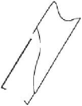
The probe can be built as shown in Figure 4.8, using a small ferrite bead (e.g., 0.1 in.
thick, 0.3 in. in outside diameter) that has been sectioned in half. The actual construction
depends on the actual ferrite that you select, but in general, 40 to 50 turns of thin enam-
eled copper wire provide suitable sensitivity. The terminals of the coil should be soldered
to the center and shield of coaxial cable. After insulating the central conductor connection,
a portion of the braid should be used to cover the assembly, thus E-
eld-shielding the coil.
The assembly can then be mounted at the end of a small plastic tube and embedded within
a glob of epoxy. For the prototype probe, a virtually
fi
fl
flat bandwidth was measured from
around 600 kHz to approximately 10 MHz.
Better bandwidth can be achieved by using a VCR magnetic head instead of the ferrite
assembly. Video heads are designed for broadband detection of magnetic
fl
fluctuations, and
for this reason they can be used for sni
ng H-
fi
elds from 2 MHz up to approximately
120 MHz with relatively
fl
flat response. To construct the probe, carefully remove one of the
Coax
Plastic Tube
Epoxy Glob
E-Field Shield
Ferrite “U”
~
0.3
Figure 4.8
A useful H-field probe can be constructed from a small ferrite bead that has been sec-
tioned in half. Approximately 40 turns of thin enameled wire are used to detect the magnetic flux
concentrated by the ferrite. A small portion of the coax cable braid is used as an E-field shield for
the coil. The assembly is mounted at the end of a small plastic tube that serves as a handle and
embedded in a glob of epoxy.


Search WWH ::

Custom Search