Biomedical Engineering Reference
In-Depth Information
and
I
l
H
(A/m)
4
π
D
2
where
l
is the dipole length in meters. In contrast with the near-
fi
eld
H
of a loop which falls
with the inverse of
D
3
, the near-
fi
eld
H
of a dipole falls of
ff
as 1/
D
2
. Similarly, the near-
fi
eld
E
of a dipole falls of
eld
E
of a loop that falls as 1/
D
2
. The
wave impedance of emissions radiated by a dipole is also a
ff
as 1/
D
3
, in contrast to the near-
fi
ff
ected di
ff
erently by frequency:
Z
π
λ
0
Z
wave
2
Compare this equation with the equation describing
Z
wave
in the near
field. The change in
wave impedance as a function of frequency in the case of a dipole is inverse to that of a loop.
In the far
fi
elds is again similar to that of electro-
magnetic radiation from a loop; that is, they decrease as the observation distance increases
as described by
fi
field, the behavior of the E- and H-
fi
Z
λ
Il
Il
D
0
E
(V/m)
2
H
(A/m)
2
D
λ
Beyond the transitional point, the wave impedance again remains constant at the value of
Z
0
. The result of a constant impedance in the far
fi
field means that the ratio of E to H com-
ponents remains constant regardless of how the
field was generated.
Of course, real-life circuits are neither ideal open wires nor perfect loops, but rather,
hybrids of these two. In a simpli
fi
ed form, as shown in Figure 4.6, a more realistic model
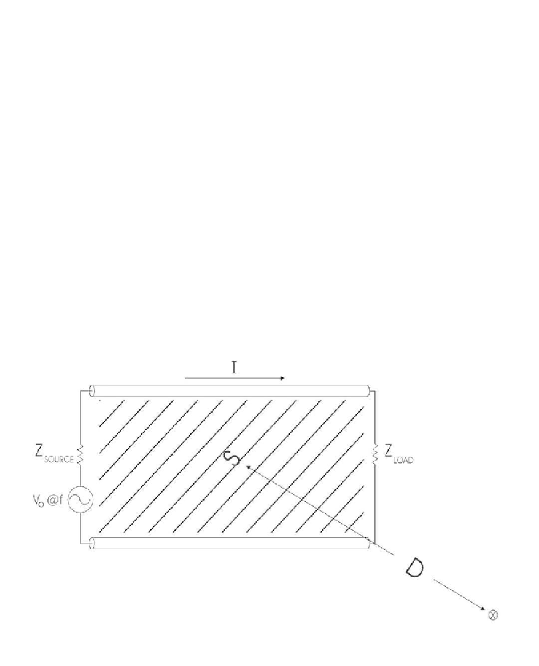
of a circuit which radiates electromagnetic emissions can assume that an ac voltage source
fi
Z
SOURCE
V
o
@ f
Probe
Figure 4.6
A simplified but realistic model of a circuit that radiates electromagnetic emissions. In it, an ac voltage source causes the flow
of a current
I
in a rectangular loop enclosing an area
S
. The voltage seen by the load depends on the source and load impedances.


Search WWH ::

Custom Search