Biomedical Engineering Reference
In-Depth Information
electrodes, through the coupling capacitance of the ISO107, through the stray capacitance
of the power supply transformer, into the power line, and back through the stray capaci-
tance of the ESU generator's power transformer. To deal with these RF currents, medical
electronic equipment often includes
filters that attenuate RF signals before they can be
detected by the circuit's nonlinearities. In our front-end protection circuit, RF appearing at
the ECG
fi
electrodes is sinked to the isolated ground by C2 and C3. C4 is used
to eliminate any remaining RF that can be demodulated di
and ECG
erentially by D1-D4 or IC1's
circuitry. Here again, currents driven by very high RF voltages must not
ff
find alternative
paths such as corona discharge or creepage, and for these reasons, appropriate spacings
must be observed.
fi
STAND-ALONE ANALOG ISOLATORS
The previous design example demonstrated the use of the ISO107 isolation ampli
er embed-
ded within a circuit to provide a signal path across the isolation barrier. In many cases, hav-
ing instead a self-contained general-purpose isolation module like that of Figure 3.4 can
simplify the design of prototype and experimental equipment. The circuit diagram for such
a module is shown in Figure 3.5. This module was designed as a stand-alone isolation board
to protect subjects connected to isolated biopotential ampli
fi
fi
ers from lethal ground fault cur-
rents as well as those originating from de
fi
brillator pulses. The heart of the module is IC1,
A
maximum at 115 V ac, 60 Hz. This performance results from the carrier isolation technique,
which is used to transfer signals and power across the isolation barrier, providing a maximum
isolation of 2500 V
RMS
at 60 Hz for 1 minute, and
an Analog Devices' 284J isolation ampli
fi
er. This device meets leakage standards of 2
2500 V
p-p
maximum continuous ac, dc,
or 10-ms pulses at 0.1 Hz.
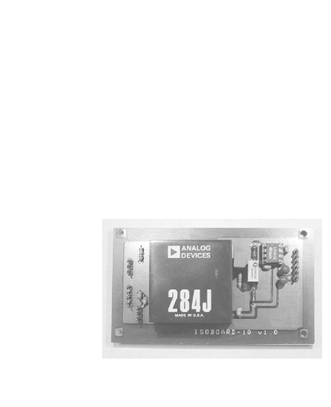
Figure 3.4
A stand-alone signal isolator can be built using an Analog Devices' 284J isolation
amplifier. The input voltage range for this module is
5V differential at unity gain. However, this
module can also be used for the direct low-level amplification of biopotential signals with a low input
noise 10
V
P-P
, medium input impedance 10
8
, and high CMR (110-dB inputs to output, 78-dB
inputs to guard). The module can generate isolated power for input circuitry, such as biopotential
signal buffer preamplifiers or instrumentation amplifiers.

Search WWH ::

Custom Search