Biomedical Engineering Reference
In-Depth Information
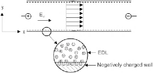
FIGURE 2.30
Electroosmotic flow in a capillary with a negatively charged wall.
Equation
(2.137)
shows that the analysis of electrokinetic flows in a microchannel network can be
replaced by the analysis of a resistance network. Electric currents and potentials can be calculated
based on the basic Kirchhoff law:
The sum of all currents at a node is zero,
The sum of all voltages in a closed loop is zero.
After determining the potentials at the nodes of the network, the field strengths in each
microchannel can be calculated. The velocity can then be determined by the given electroosmotic
mobility.
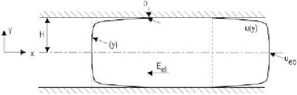
2.6.1.3 Electrokinetic flow between two parallel plates
Figure 2.31
shows the model of electrokinetic flow between two parallel plates. The velocity distri-
bution
U
(
y
) of an electrokinetic flow between two parallel plates can be derived from the Navier-
Stokes equation. For further simplicity, the variable
U
(
y
) is introduced:
u
eo
Jð
y
Þ
u
ð
y
Þ¼
U
ð
y
Þ
:
(2.139)
z
FIGURE 2.31
Model for electrokinetic flow between two parallel plates.


Search WWH ::

Custom Search