Biomedical Engineering Reference
In-Depth Information
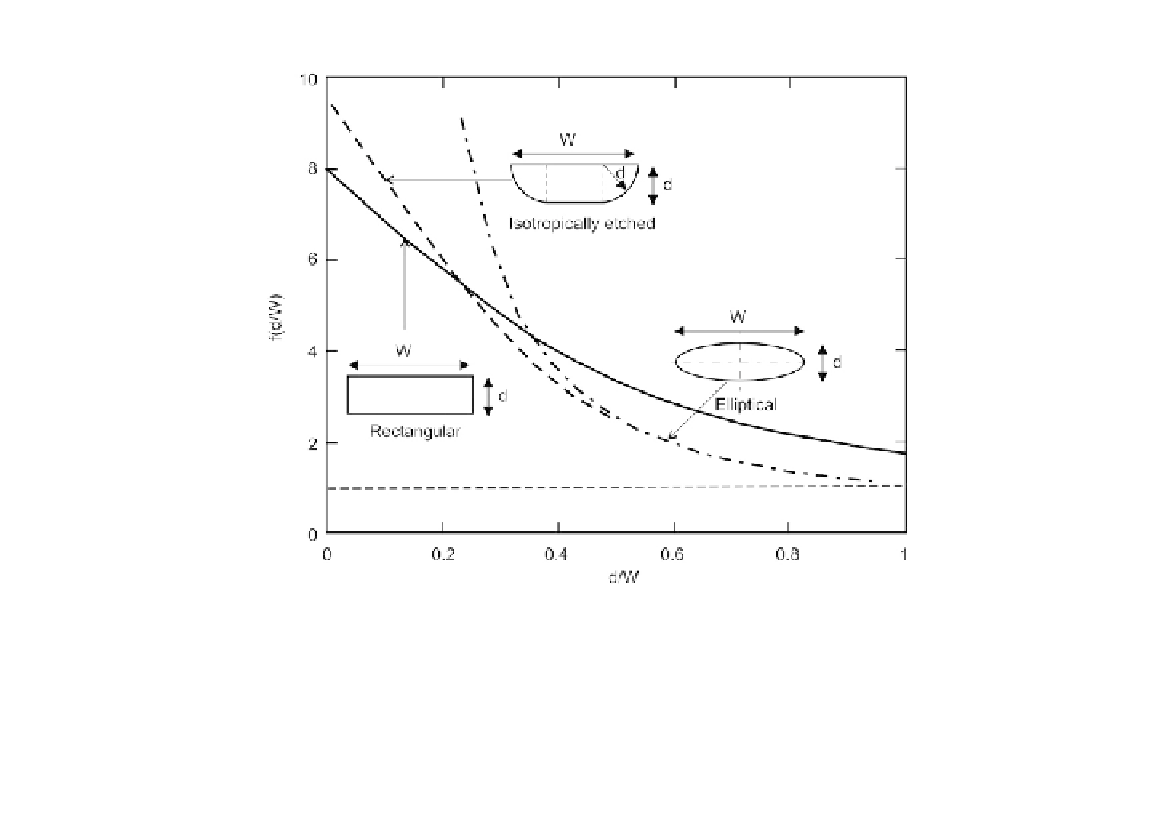
FIGURE 2.12
Dispersion factor f for typical channel geometries versus aspect ratio d/W (after
[23]
).
Dutta et al.
[23]
introduce a factor
f
into
(2.77)
to consider the three-dimensional effect of Taylor
dispersion:
d
2
u
2
210
D
f
D
¼
D
þ
;
(2.78)
where
d
1 for the case of the parallel plate model. The factor
f
is a function of the aspect
ratio
d
/
W
, where
d
is the characteristic length of the shallow channel height and
W
is the channel width.
Based on this definition, the longer cross-sectional dimension is considered as channel width; thus,
d
/
W
¼
2
h
and
f
¼
1. Using the Aris approach
[12]
and numerical simulation, the factor
f
can be determined for
different geometries.
Figure 2.12
shows the dispersion factors of typical channel geometries as
a function of the aspect ratio
d
/
W
.
Because of the velocity gradient at the sharp corners of a rectangular channel, factor
f
increases
from
f
¼
1.76 in the case of a square channel cross section (
d
/
W
¼
1) to
f
¼
7.95 in the case of a shallow
channel (
W
[
d
). The factor of an elliptical channel cross section can be calculated explicitly as:
W
d
2
24
24
3
2
5
3
4
210
192
þ
;
f
¼
(2.79)
24
12
3
2
p
1
d
2
W
2
where
3
¼
=
is the eccentricity of the geometry.


Search WWH ::

Custom Search