Biomedical Engineering Reference
In-Depth Information
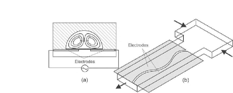
FIGURE 7.23
Mixing based on electrokinetic disturbance and chaotic advection: (a) channel cross section with secondary flow;
(b) concept of the micromixer.
The concept of sequential segmentation can also be implemented in an electrokinetic flow. Tang
et al. utilized switching of electrokinetic flow to generate short segments of solvent and solute in the
mixing channel.
[38]
Electrokinetic segmentation was capable of creating stable fluid segments in the
mixing channel at a frequency between 0.01 and 1 Hz. However because of the lack of a distributed
velocity profile in the channel cross section, there was no Taylor dispersion and mixing in flow
direction still relies on molecular diffusion.
The concept of controllable zeta potential was reported by Lin et al.
[39,40]
.
Fig. 7.24
shows the
different configurations of shield electrodes. The groves for the electrodes are etched in glass with
the microchannels in the same process. A gold/chromium layer was sputtered and etched to form the
shield electrodes. The microchannels are sealed by another glass plate using thermal direct bonding.
The mixing channel have a width of 150
m
m or 200
m
m. In the case of parallel electrodes shown in
Fig. 7.24
(a), the electrodes are 200
m from the channel wall. Inclined
electrodes shown in
Figs. 7.24
(b) and (c) have their distance varying linearly from 130
m
m long and are placed 130
m
m
m
m.
Figure 7.24
also shows the simulated streamlines of the electrokinetic flows with these three electrode
configurations. The simulation data shows clearly that the area with controlled zeta potentials generate
a flow opposite to the main flow, leading to recirculation at these areas. While parallel electrodes lead
to a relatively regular streamlines, a gradient in zeta potential causes very complex stream lines, which
possibly lead to chaotic advection. Experimental results showed that the configuration with zigzag
electrodes shown in
Fig. 7.24
(c) delivers the best mixing performance.
Wu et al.
[48]
controlled the zeta potential by embedded electrodes. The electrodes are made of
a 200-nm-thick aluminium layer and take the asymmetric herringbone shapes,
Fig. 7.25
. The elec-
trodes are insulated from the mixing liquids by a 500-nm silicon oxide layer. The driving electrodes for
the mixing streams are made of a titanium/gold layer. The mixing channel were molded in PDMS,
which is bonded to the silicon substrate with all the electrode structures using oxygen-plasma-assisted
bonding. Similar to the work of Lin et al.
[39,40]
, the zeta potential at the bottom surface of the mixing
channel can be controlled by shield electrodes made of aluminium. Mixing occurs when a square wave
with peak voltages of 100 V and -50 V were applied at 0.5 Hz.
m to 520


Search WWH ::

Custom Search