Biomedical Engineering Reference
In-Depth Information
microvalves are implemented by polysilicon heaters on the quartz cover plate. The heaters generate
vapor bubbles, which in turn drive the liquid. The micromixer is characterized by the distance between
a source and a sink 2
a
, the distance between the two source-sink pairs 2
b
, the pump chamber diameter
p
2
l
and the source-sink strength
Q.
Normalizing all other length by
a
results in the aspect ratio of the
mixing chamber
a
;
l
/
a.
A too large aspect
ratio
a
decouples the two source-sink pairs. A too small aspect ratio makes the two pairs work again
each other. Both extreme cases do not lead to good mixing in the chamber.
Cola et al.
[18]
realized the pulsed source-sink concept in a much larger scale. The mixing chamber
measures 21 mm
¼
b
/
a
and the dimensionless size of the pump chamber
b
¼
71 mm. The sources and sinks are driven by external syringe pumps. The
switching valves are external solenoid pinch valves. A similar device was reported by Raynal et al.
[19]
. The mixing chamber measures 15 mm
15 mm. These relatively large pulsed source-sink
mixers are needed for hybridization reactions of DNA arrays.
Moving parts in the mixing chamber or mixing channel can actively cause pressure and flow
disturbance in the mixing channel. Suzuki and Ho
[20]
demonstrated the miniaturized version of
macro scale magnetic stirrer. An electrical conductor generates a magnetic field, which in turn attracts
magnetic beads of 1-10
m in diameter. The disturbance caused by the magnetic field leads to chaotic
advection in the otherwise regular flow.
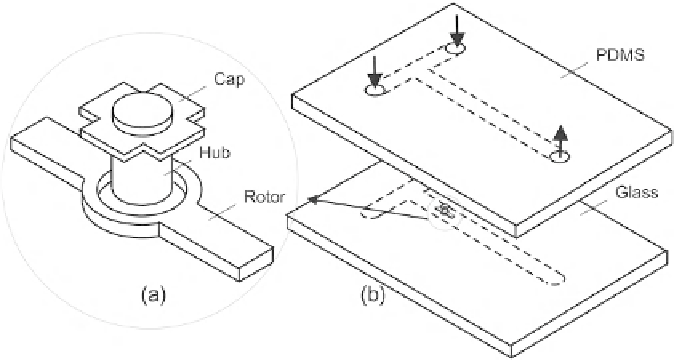
Lu et al. integrated a magnetic micro stirrer inside the mixing channel
[21]
. The micro stirrer was
fabricated by electroplating of iron/nickel alloy on a glass substrate. Sacrificial layers made of
photoresist and copper were used for defining the rotor, the hub, and the cap. The micro stirrer is in
total 25
m
m tall. Tips of a 0.5-
m
m defines a gap between the rotor and the substrate,
Fig. 7.14
. The
microchannel network was fabricated in PDMS using soft lithography. The mixing channel had a cross
section of 70
m
m. The micromachined stirrer is placed at the interface between two liquids
in a T-mixer. Stirring speeds between 100 and 600 rpm were achieved with an external magnetic field.
The advantage of this design is that there is no need of electrical interconnects to the mixing device.
m
m
750
m
FIGURE 7.14
Active micromixer with integrated micro stirrer: (a) the stirrer, (b) the micromixer.


Search WWH ::

Custom Search